Federal FA-5238 (Dept of Commerce Limiter)

GroupDIY Audio Forum

Help Support GroupDIY Audio Forum:

This site may earn a commission from merchant affiliate links, including eBay, Amazon, and others.

OneRoomStudio

Well-known member
GDIY Supporter
Joined
Jul 8, 2004
Messages
834
Location
Minneapolis, MN, USA
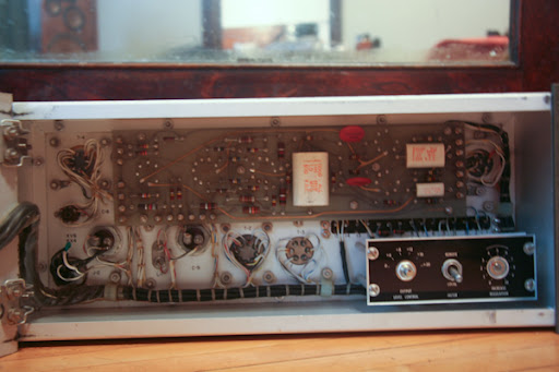
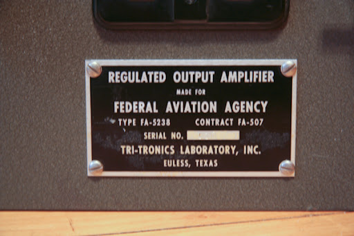
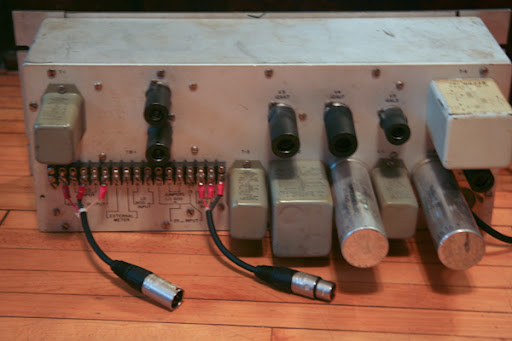
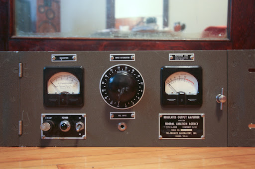
A client of mine bought this unit thinking it was one of the 864/u limiters, and was disappointed to find out that it's not. He wants me to see if I can turn it into something more useful (ie a preamp or compressor). I've searched around, but can't seem to find a schematic. It already has a mic input which appears to be wired to an input transformer (all the wiring is laced together, which is beautiful, but not easy to trace), and it has a section labeled output regulation, but I'm not entirely sure how this is implemented without spending some more time with it. It's very possible that there's some sort of side chain and the "regulation" could be some sort of vari-mu style bias regulation. It's also possible that it's simply a line amp with a mic input and an output control labeled "regulation." The thing is a work of art though, and it's certainly beefy (three transformers, a choke, and six tubes). The tube compliment is: 6X4 rectifier, 5726(6AL5), 6189W(12AU7), 12AX7WA, and a pair of 6AU6WC's. The hardest part about getting this going is finding a suitable replacement for the chassis-mount 4uF @ 600V caps. If anyone here knows anything about this unit or has any ideas, I'd love the input. If anyone has a schematic, you'll make me a very happy guy. Here are some pics:

**Doug identified this as a Maxson Dept. of Commerce Limiter (thanks again)

For those of you who can't see the pictures, here are some links:
http://lh6.ggpht.com/_IAJCNj0PC6g/SgyVd_Ei0WI/AAAAAAAAAPc/VL-A-eOnEl4/Federal1.jpg
http://lh4.ggpht.com/_IAJCNj0PC6g/SgyVeApLMBI/AAAAAAAAAPg/Cbpy293Ep6Q/Federal2.jpg
http://lh4.ggpht.com/_IAJCNj0PC6g/SgyVeIzDQcI/AAAAAAAAAPk/NENW-KeLU-0/Federal3.jpg
http://lh5.ggpht.com/_IAJCNj0PC6g/SgyVeV-P6CI/AAAAAAAAAPo/dQqJkgmB8LM/Federal4.jpg
Federal1.jpg

Federal2.jpg

Federal3.jpg

Federal4.jpg

 
There's a schematic out there.  Search online for Dept. of Commerce limiter.  There are multiple variations which are all the same circuit.   Don't change a damn thing about it.  If he doesn't like it, resell it.  People pay plenty.  
 
Doug, thank you! Since it had a different model number and didn't say "Department of Commerce" on it, I would have had no idea that that's what it is. I had never actually seen a DoC limiter before, but this is definitely it. I found the schematic and it's pretty much identical with only a few minor differences.

My next question is one that you've addressed before, but maybe you have some new or different information now. My client complained about two things after he tried it out. First, he couldn't get it to "compress," which I think stems from the regulation being set wrong, and perhaps bad gain staging. The second complaint seems to be a common one - the bandwidth is poor. I read in another thread that you didn't think there was much that could be done about this, and that it's best left the way it is. I certainly appreciate this view point, and I'm sure you're right, but I'm curious if your experimentation with larger coupling/filter caps helped at all. Did you ever explore altering the feedback network, or did you decided that it wasn't worth pursuing? After looking at the frequency response noted on the transformers (300-4K), I realize that this may be a fool errand, but if I can get even a little more bandwidth out of it, I would be very happy.
 
All the iron but the repeat coil on the output tests with very limited range out of circuit.  You can bump up the coupling caps to get a little more, but not much.  It will motorboat pretty quickly.  I added a shitload of additional filtering in pursuit of more low end, and no amount was sufficient.  You could design a heavily eq'd feedback network, but I don't think you'd get very far there either.  They are what they are, and best left to those who desire them.   It's a bit of a travesty that people are paying so much for them, based only on rumour rather than personal listening.     Have you tried new tubes?     You shouldn't have to replace the oil caps at all, unless they are bad.   Don't even try unless forced to.   I can't see these pictures at all.  
 
They made a "full" bandwidth version and a "speech" bandwidth version.  I (unknowingly) bought a speech version about 6 or 7 years ago on ebay for $175.  Turret board construction.  I don't think I've ever seen a circuit board version before seeing the one above.  Beautifully built machine, but fairly useless in application.  I tossed it on ebay a year or two later and it somehow got up to $964.  I even disclosed the limited bandwidth!  You can never pay too much for the tube warmth, huh?


It's a Tri-tronics.  Not Federal or Maxson.   First I've seen with circuit board versus turret board too.  

MikoKensington said:
They made a "full" bandwidth version and a "speech" bandwidth version.  

I hear this story in regard to the AM-864/U units made by the Federal Television Corporation.  This thing is totally unrelated, outside of being a US Govt. contract piece.  I've never seen any version of this amp that was full frequency.  
 
OneRoomStudios said:
A client of mine bought this unit thinking it was one of the 864/u limiters, and was disappointed to find out that it's not.

Does he want to make me an offer on mine?!?  ;D

Michael
 
emrr said:
It's a Tri-tronics.  Not Federal or Maxson.   First I've seen with circuit board versus turret board too.   

MikoKensington said:
They made a "full" bandwidth version and a "speech" bandwidth version. 

I hear this story in regard to the AM-864/U units made by the Federal Television Corporation.  This thing is totally unrelated, outside of being a US Govt. contract piece.  I've never seen any version of this amp that was full frequency. 

They exist.  I talked to Michael Brauer about his, upon receiving mine.  He's the one that told me about the two versions.  And there were actually 2 model numbers on mine.  CA-1589 on the face and I think the other was CA-1532, located on a service note inside.  It's been a while. 
 
Cool.  I know I've seen at least 3 different manufacturers of this basic circuit.  Michael's first DoC actually came from me off ebay in 2002; restored and working for $400.  
 
I kinda wish I still had mine, because I do a lot of parallel compression these days.  I think crushing a snare in parallel might sound cool with one of these.  That could be my excuse for having such a cool looking piece. 
 
I did some experiments with passive bandpass filters in front of other full range tube limiters I have, and felt that I could really achieve the same basic thing that way, versus dedicating a telephone amp to the job.   Seemed a much cheaper way to go at the time.  
 
Here's a freq run on a Tri-Tronics version.  This one is lower serial # and different transformers from the first I had, but response basically the same.  Totally stock, into the 600 ohm HI input.  The 600 ohm LOW input is a 27 dB 600 ohm U pad feeding a 25 ohm winding, for even more high end loss!   These really need a bridging pad feeding the 600 ohm HI input, to avoid saturating the input transformer which is rated for 0 dBm level.     I'll get to revisit freq improvements on this one for a client.  

 
Decided to go with a switchable 30 dB U pad in front of the 600 ohm HI input.   The Tri-Tronics uses a 680K release resistor rather than a 1.5M, and adds 100K in series from 6AL5 to timing cap, for slower attack.    I'm installing adjustable attack and release on another interior panel, along with pad switch.   Note the 'regulation' control is ratio.   This can be moved off the subpanel and put on the forward one, so you don't have to adjust it with a screwdriver.  Simply move it; no soldering needed.  

Pics soon.  
 
Here's some detail on the bottom end, showing the stock low end (yellow), the most I attempted to gain (red), and the position I settled on (orange).     As always, the ripple in the curves is a product of the pink noise resolution, not the unit itself.  

My final chosen tailoring resulted in the following improvement over the stock EQ:

0.75 dB better at 125
2.5 dB better at 63
3.7 dB better at 31

This was achieved by changing the coupling caps between the 12AX7 and 12AU7 to 0.0022 versus stock 0.001, and adding 1 mfd of filtering at the B+ branch point that supplies the 12AX7 and the 6AU6's.   As soon as you raise the value of the coupling caps, you get motorboating unless you add B+ filtering at this point.

The red plot was achieved with 0.1 coupling caps, and that required addition of 20 mfd filtering at the same position to stop motorboating.   This suggests there is little point in going very far with the bandwidth between the iron, as the iron simply overrides any frequency gains beyond a certain point.   The additional low frequency passed with this mod produced excessive distortion in the gain reduction.  You could tailor that back out by introducing a HPF stage between the side chain rectifier winding and the 6AL5, but I felt that you would begin to effectively undo the very thing that people like about these in the first place; the production of additional presence when used as a parallel device in a mix.  

The stock response dials out the significant low frequency distortions this unit produces; it's a well balanced house of cards. I settled for doubling the bandwidth within the output amp stages, which added noticeable intelligibility to kick drums and bass with a minimum of increased distortion.

You could go so far as to also add cap tailoring to the feedback to get more lows and highs, but then you'd change it from a special effect unit to a low quality higher bandwidth unit that no longer did anything terribly useful.   You'd definitely have to add the HPF in the side chain, and there's probably only so far you could go before it would motorboat no matter what.  

I decided I like the ratio set somewhere from the mid point on up to limiting best.  It becomes more obviously distorted and grainy with the lowest ratio ('more regulation').   Additional attack and release ranges are fairly soft in concept.  The sound changes, but it's fairly vague and imprecise in effect.  

I tried to spot the schematic for the other version so I could link it, but I can't find it right now.  Anyone have the link?   My drawing and some pics are in a later post here.
 
Nice work.


When going from 1uF to 20uF did you do it incrementally or was the mathematical relationship for the correct value already known?  Just curious where it (or would've) started to take off in between 1 and 20.
 
Some people like to spend excessive time doing math.  Some people do it quickly.
;D
I have dangerous test leads laying about, and slip additional mfd's in until the motorboating stops.  Or change a coupling value and start taking filter mfd's away until it flips out.   That's fastest for me.   10 mfd didn't fix it with the 0.1 coupling, and 20 did.  1 mfd was plenty with the 0.0022, but stock was not okay with the additional octave the 0.0022 provided.  
 
Oh yeah!  Hard to beat empirical evidence. . . and nice thick insulation on the alligators!
 
Frequency plots of an earlier octal tube variety. 

-3 dB points of 80 and 8K.
Original response (white), and the modified response (green). 
Red represents the most bass I attempted, but abandoned because of significant increases in distortion. 

This unit has an LC notch filter at 10K5 kHz that kills the top.

Front looks exactly the same. 
 
Let us know exactly what you end up with for a pad. I use mine on the low input and deal with it so as not to risk damaging the thing, but I'd love to get just the tiniest bit of top end back.

The bottom end's fine for me. I almost always use the thing in parallel. It can make for some interesting phase relationships.


Latest posts

Back
Top