Drip V72 finished!

GroupDIY Audio Forum

Help Support GroupDIY Audio Forum:

This site may earn a commission from merchant affiliate links, including eBay, Amazon, and others.

JoleFIN

Well-known member
Joined
Feb 23, 2009
Messages
138
Location
where's the party at
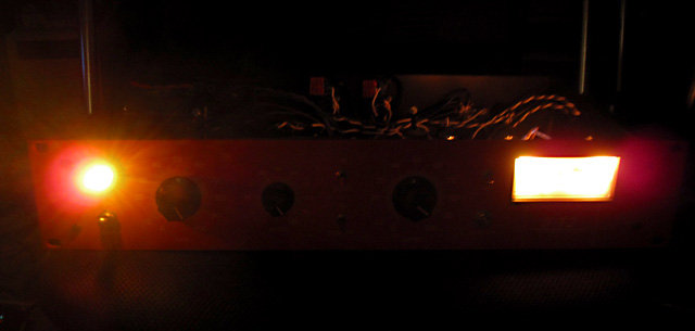
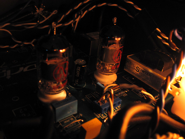
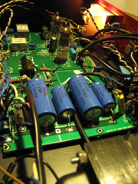
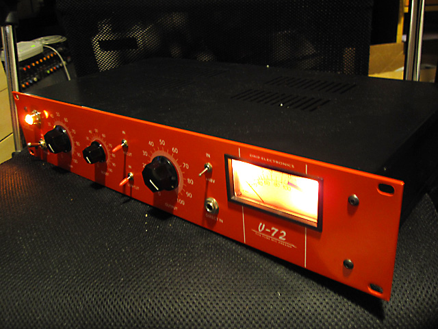
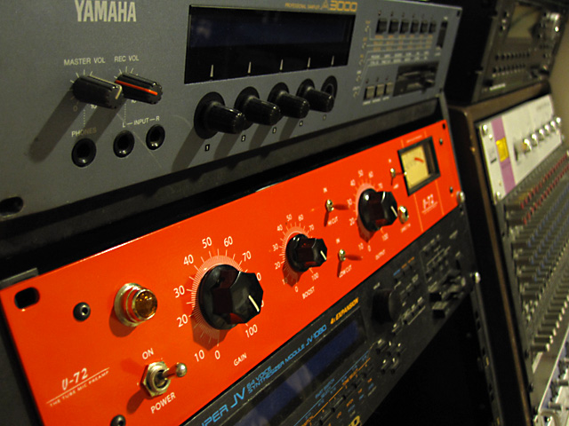
I'm nearing completion with a Drip V72. Sound is passing through, but it's so silent I need to turn both input and output pots to max and then gain +30db from Mackie to get around -20dB when recording a normal speech up close to the mic (some Oktava tube for the test drive). The VU doesn't move either, but if get to "brum" the device the needle moves upwards a bit so the VU seems to be working ok. The Boost pot is a series of 12 resistors on a 12 position switch, and it starts distorting the sound (a warm tubey distortion) if turned upwards from the 'zero' position.

So there's not enough gain before the VU but too much gain before the tube "boost"? Anyone have any ideas where should I be looking towards to fix this/these problems?

-J
 
Anyone? Anyone familiar with the build or with the JJ EF806S tubes ? I can't reach Drip's Greg, and I can't register in the Drip forum to ask about this issue there, since the registration needs an activation from the admin, iow. Greg and he seems to be absent at the moment. Hope everything's ok with him, haven't heard of him for a while.

I'm using the JJ EF806S tubes http://www.jj-electronic.com/pdf/EF806S.pdf
I measured the tubes' pins and don't think the voltages here are as they should be :

Tube #1
1. 88.5V
2. 0
3. 1.25V
4. 28.0V
5. 28.0V
6. 0.25 -> 0.05? (this one goes downwards when measuring, as if a cap was loosing it's load when measuring.. starts from around 0.25V and the emptying of the load slows down gradually when nearing 0V/"infinite")
7. 0
8. 1.25V
9. 0

Tube #2
1. 51.2V
2. 0
3. 1.09V
4. 28.0V
5. 28.0V
6. 74.0V
7. 0
8. 1.09V
9. 0

Shouldn't I have a 6.3V heater voltage going on somewhere, on pin 5?

On the PCB you have this point that you should adjust with a relevant resistor to meet 260V-275V area and I'm measuring 280V there, but don't think this small over run would cause such an issue.
 
ok so you can't register at his support forum as the admin is not available at the moment. Since it is a DIY build here are a few things to go over.

I would start off by checking for cold solder joints
2. check your wiring
3. check your PSU

That is usually the bigger issues happen with a DIY build...

Low amplitude with distortion would have me looking towards the tubes or something in relation to the tubes like your heaters not working.
 
If I remember correctly I had a problem with the choke - I'm using a sowter choke - I had to connect two pins of the choke with a wire after soldering it to the pcb. Sorry... Its quite a while ago...
andreas
 
Below are test readings on my Drip V72, which you can use for reference. The choke completes the B+ circuit for tube V1 (output stage) so you should check it out. I am using the Lundahl choke on mine. I see a 54VDC voltage drop across the choke with tubes in.

EDIT: Also make sure you are using the correct tubes. The vintage V72 uses EF804S while the Drip uses E83F. These are electrically similar (identical?) but the pin-out is different so they are not interchangeable without rewiring PCB traces.


Voltage Checks: tubes removed, no input/output connections
---------------------------------------------------------------------------
Power Transformer primary (black/black): 121.5 VAC (house voltage)
Power Transformer high voltage secondary (red/red): 570 VAC
Power Transformer heater tap (green/green): 7.2 VAC

B+ test point (R25) to ground: 343 VDC
DC Heater offset (green/yellow center tap to ground): 33.3 VDC


Voltage Checks: tubes installed, no input/output connections
---------------------------------------------------------------------------
B+ test point (R25) to ground: 258 VDC
DC Heater offset (green/yellow center tap to ground): 29.6 VDC

Tube 1 (output stage) measurements:
Heater voltage across pins 4 and 5: 7.1 VAC
Plate (anode) pin 6 to ground: 204.6 VDC
Supressor grid pin1 to ground: 204.6 VDC
Cathode pin 3 to ground: 3.27 VDC
Supressor grid pin8 to ground: 3.27 VDC


Tube 2 (input stage) measurements:
Heater voltage across pins 4 and 5: 7.1 VAC
Plate (anode) pin 6 to ground: 61.6 VDC
Cathode pin 3 to ground: 1.16 VDC
Supressor grid pin1 to ground: 48.7 VDC
Supressor grid pin8 to ground: 1.16 VDC


--Peter
 
morbleu said:
If I remember correctly I had a problem with the choke - I'm using a sowter choke - I had to connect two pins of the choke with a wire after soldering it to the pcb. Sorry... Its quite a while ago...
andreas

Same here, got a Sowter.. but according to the Drip's build manual PDF, with Sowter it's straight forward plug'n'play, whereas with Lundahls you need to do some wiring. I'll check the voltage drop over the choke, maybe it reveals something out..


peters said:
EDIT: Also make sure you are using the correct tubes. The vintage V72 uses EF804S while the Drip uses E83F. These are electrically similar (identical?) but the pin-out is different so they are not interchangeable without rewiring PCB traces.

The build manual suggests using Tungsol EF806, and the JJs should be a good replacement for these. The tube #2 spot seems to fit the area quite ok according to the voltage comparison with the values you have measured on your unit, but tube #1 is out of "boundaries"... it doesn't change hardly anything if I swap them around, so I think both of the tubes are good to go with but there must be something with the resistors or so.


peters said:
Voltage Checks: tubes removed, no input/output connections
---------------------------------------------------------------------------
Power Transformer high voltage secondary (red/red): 570 VAC
Power Transformer heater tap (green/green): 7.2 VAC
B+ test point (R25) to ground: 343 VDC
DC Heater offset (green/yellow center tap to ground): 33.3 VDC

It's in the correct playground here I think, with 525VAC on red/red and 6.1VAC on heater tap. B+ gave me 316VDC and DC Heater offset 29.6VDC ... It seems the tube #1 is not getting anywhere right readings. Heaters are ok with 6.0VAC? There should be 200VDC on pin 6 where I have almost 0VDC, and 200VDC on pin 1 where I have 88.5VDC .. Need to check the resistors that affect the tube #1, but which ones are the exact ones?

Thanks for these Peter!

-J
 
Do a search for the data sheets for the (2) tubes and look at the pin-out diagrams.
The plate is on pin 6 for one and pin 7 for the other:
http://tubedata.tigahost.com/tubedata/sheets/009/e/E83F.pdf
http://www.shinjo.info/frank/sheets/128/e/EF804S.pdf

If you look at the V72 schematic you will see that the choke acts as the "resistor" feeding the plate for the output tube. If the choke is open circuit you will get no voltage on pin6. Have you checked the resistance across the choke (unit unplugged)?

--Peter
 
Yeah the manual states ef804 is not compatible due to different pin out but also says ef806s to be the correct one.

I don't get any sense from the choke, it gives me unstable resistance (even negative resistance according to the meter?)
 
Ok  the ef806s is ok; I was confusing with ef804.

Sometimes the meters don't get along with the choke. It might be the auto ranging thing.
Another approach would be to to pull the output tube and see if you then get the full voltage at pin 6, which would indicate that the choke is working.

Also check out resistors R22, R23, R24 which could potentially cause issues in the output tube voltages.

Resistors R12, R14, R15, R16 would be for the input tube voltages.

They are all somewhat tied together though so one wrong resistor can effect a lot of things.

Reasonable schematic/manual here (long URL):
http://audio.kubarth.com/rundfunk/getfile.cgi?f=C%2C3(V-CDU-C4U-5]%22%3CF%25U%3BF)U8V%40O%3B6%25I%3A%26%25K7U8W%2CBYP9%268%60%0A

Follow the lines... the main B+ supply comes from R25 which sits between the power supply and everything else.

--Peter
 
I measured the pin 6 without the output tube and it's still giving the same 0.2VDC .. Could I be having problems with the choke here? It's the Sowter iron, so two of the pins remain unused (correct?).

The resistor seem ok but I will double check them next.

PS. Is there a reason for having no JUMP 5 in this installation or is it still in an unfinished state?
http://la2a.com/v72/BOARDV72.jpg

 
Un-plug. Take a long coffee-break (to be sure the caps are fully discharged).

Put a 10K resistor across the choke.

Measure the choke. If it is good, but the huge inductance was baffling your DMM, now it may settle-down and read maybe 1K. If it is bad (most likely mis-connected), at least you have the 10K to dribble juice to the plate.

Now power-up and read plate voltage. 0.2V is wrong. With resistor, full B+ is wrong. Something in the middle means the tube is doing its thing fine, you need to suss-out your choke.
 
Regarding the jumpers, you generally need all of the numbered jumpers installed (including J5).

You can leave out J2 if you need to put a really big C32 cap in there, and it acts as the jumper.

See my pics here:
http://home.comcast.net/~ps8899/v72/

Depending on input setup you might leave out R11 but deal with that after you get the high voltage stuff straight.

--Peter
 
Check out Drip's forum. I had this same issue. Well, it sounds the same.

With the input pot installed, the input impedance gets really funky. Try routing a line-level signal from your sound card into the unit. Sound better? That (to me) would point to an impedance issue. There's a well documented problem that myself and a few others encountered. I solved it by modifying the wiring of the input transformer from 1:20 to 1:10 and removing both the input and output pots.

Check one of the posts here:

http://dripelectronics.com/forum/viewtopic.php?f=4&t=10&start=10

Might not be your issue but it sounds like what I went through!
 
PRR said:
Un-plug. Take a long coffee-break (to be sure the caps are fully discharged).

Put a 10K resistor across the choke.

Measure the choke. If it is good, but the huge inductance was baffling your DMM, now it may settle-down and read maybe 1K. If it is bad (most likely mis-connected), at least you have the 10K to dribble juice to the plate.

Now power-up and read plate voltage. 0.2V is wrong. With resistor, full B+ is wrong. Something in the middle means the tube is doing its thing fine, you need to suss-out your choke.


Ok, screw long coffee breaks, I soldered the 10k resistor with tongs and avoided touching anywhere :)

And voila, we have the sound and the loudness! At least with headphones it sounds all good now, just a little brum with maximum gains.. might be fixed with positioning of cables (now it's hanging loose freely, a mess). I'm wondering what's wrong with the choke (if there's something wrong, at least it's not giving anything more than 0.2V outwards), it doesn't measure anything (no ohms.. no connection between the pins). Already contacted Sowter how to proceed from here.

Huge thanks everyone! I'm feeling relieved! Though I was thinking it cannot be a soldering failure here (well of course it can but I don't want to admit such possibility to myself) because it is not a complicated circuit, it's a lot simpler than the GSSL and 1176 ones that I made last year. Now on to replacing the choke... and then finishing touches :)
 
If using the sowter choke make sure its in there the correct way. Otherwise it may not be in the circuit.
I think there are details in the Drip manual.

--Peter
 
Yes, did check it multiple and multiple times just to be certain about it. Desoldered it off the PCB carefully, it doesn't have a connection between the pins but the wire is not cut anywhere near the pins, since the wire is attached and it doesn't come out by pulling carefully. Sowter is sending me a replacement and I'll send this one back to them for further investigation of what's wrong with this piece.

PRR spotted the problem right away, dang :)

-J
 
Finally! I ordered the case and the PCB both in May last year, but didn't hurry with it at all though. Great to have it off the desk, and finished with such a nice sound! :)

IMG_5630.jpg

Added some extra luminousity with two bonus bulbs aside the festoon (digicam didn't like the lighting conditions that much though)


IMG_5632.jpg

Moody


IMG_5640.jpg

It's a "little" bit of a rat's nest but there's no humming after I told her she's grounded.


IMG_5648.jpg

I love this color


IMG_5650.jpg

With her new friends, awwww <3 <3
 
Back
Top