G7 Mic nearing completion need help wiring PSU

GroupDIY Audio Forum

Help Support GroupDIY Audio Forum:

This site may earn a commission from merchant affiliate links, including eBay, Amazon, and others.

marktokach

Well-known member
Joined
Feb 5, 2008
Messages
169
Location
New Braunfels, TX
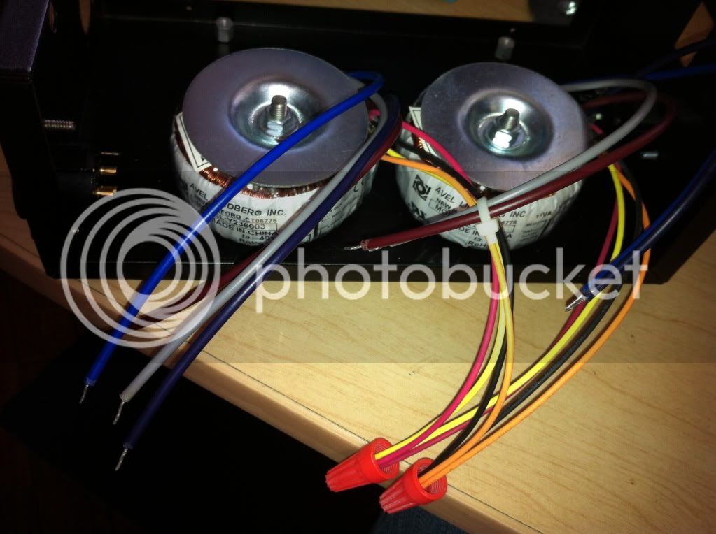
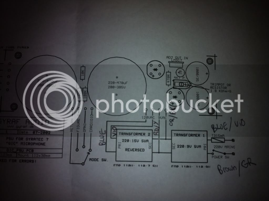
Hello everyone. I just got back to finishing my two G7 mics after some time away from DIY. I believe I understand everything except wiring the 2 toroidal transformers. I have searched, and searched, and I hope someone will point me to the right page, and can't seem to find very easy to understand instructions on how to wire them. They are avel lindberg brand. Is there a pic some where of what color wires go where? I have avel data sheet and the 5 va is hooked up primaries and secondaries parallel connected. b/v  g/br  bl/or  red/ y. The other one i have r/y or/bl connected together and to the r/y or/bl of the 5 va. Gr/Br of 5 va go to hot of IEC connector. bl/vi to ground of IEC. etc. If this is even right so far... it's all I understand so far. Thanks, Mark.

Image.jpg
 
Hey There,

If you snap a picture of the wiring diagram on the side of the transformer, or direct us to a data sheet, we can help you better. But, what you want is 115V(this will be 2 115v windings in parallel):9v to 15v:220V(this will be 2 115v windings in series).

Best,

Ben
 
Ok.

For the Y236001: Primaries in parallell, and secondaries in parallell. So connect blue to violet, gray to brown, black to orange, and red to yellow. Connect the primaries to your (120v) wall voltage, through a proper fuse and switch. You will need to run wires from the secondaries (black/orange and red/yellow) to the 9VAC (heater) input on the power supply pcb, as well as connecting them to 15v the windings on the Y236003.

For the Y236003: (primaries and secondaries get confusing here, because this transformer is wired backwards, so I will refer to a winding by it's voltage). 15v windings in parallell, 115v windings in series. So connect gray to violet, black to orange, and red to yellow. You will connect the 15v windings of this transformer to the 9v windings of the other transformer - connect black/orange to black/orange and red/yellow to red/yellow. You will connect the 115v windings in series to the 120VAC input on the power supply pcb.

So what you have done so far is correct, but you will need to add wires at those wire nuts to the heater inputs.

Best of luck,

Ben
 
That is correct, EXCEPT, blue and brown on the Y236003 should be connected to the 120VAC input on the PS pcb! Violet should be connected to grey.

Best,

Ben
 
That is what i meant to write and i messed it up on the paper! I already have gray and violet zip tied. Thanks again, this helps me better understand transformers. I will read up on them to try to understand. I guess it doesn't matter which holes the blue or brown go in (left or right) on the pcb 120 vac input on the pcb because it's ac. Thanks once again.
 
I am blowing fuses as soon as I turn it on. I have fused IEC connector hot hooked to spst switch then to brown and gray wires. IEC neutral hooked to blue and violet. Is that right at least? I am using .315 amp fast acting fuses. Are these correct type or do i need slow blow?
 
yes on the slo-blo as those big caps can cause a bit of inrush current,

do you have a variac? bring it up slow and monitor transformer output side with voltmeter, no voltage equals a short or swapped phase.

what i do when i have these problems is to start all over, as this is the fastest way of finding the location of the problem.

try just on transformer with no load, then two transformers with no load, then try one load at a time, in other words, you try to isolate the problem by re constructing the pwr supply in increments, til you find the place where you are blowing fuses at.
then you will have the answer as to what part of the circuit needs fixin.
 
Have you  a bad transformer? I received one from another supplier (same country of origin) with no secondary voltage.
 

Latest posts

Back
Top