Measuring frequency response

GroupDIY Audio Forum

Help Support GroupDIY Audio Forum:

This site may earn a commission from merchant affiliate links, including eBay, Amazon, and others.

letterbeacon

Well-known member
Joined
Jul 12, 2009
Messages
642
Location
London, UK
So I'm at the stage of my pre amp build where I want to measure the frequence response of it and adjust the circuit accordingly.  I've seen emrr and others use Spectrafoo to measure their pre amp's frequency responses so I think I'm probably going to go down that route.  Thing is, I've been reading the Spectrafoo manual and I can't for the life of me work out how I would do it!

Are there any online tutorials that I've missed when I've Googled or would someone be kind enough here to run through the basics?  I know I've got to build a pad to make the impedance of my Fireface line outs mimick a mic, and I know I need to do sine sweeps, but the rest I'm finding slightly impenetrable!

Any help would be much appreciated!
 
You'd have to have spectrafoo complete to get testing abilities. 

A mic pad is useful for testing, but you should also see what you get connecting directly. If you have a published output Z spec for your interface, you can see what adjustment is needed, possibly nothing, possibly a small amount of series resistance to raise it to 150R.

I use pink noise for most tests, with a longer settling time on the receiving end.
 
Hmmmm, annoyingly it looks like RME have only published the input impedance (10k/ 470k - line/ instrument) for the Fireface 400.  Should I use a U pad on the safe side anyway so I know I'm feeding it 150 ohm impedance?

With Spectrafoo I was planning on using their demo version or maybe finding an alternative if the demo couldn't do it either.  But with whatever software I end up using, the theory is the same right?  I run with a sine sweep or pink noise through the amp, the software picks it up and maps the difference between the input and the output on a graph right?

Thank you.
 
Assuming the pad doesn't introduce any anomalies, you can do a great job with RMAA: http://audio.rightmark.org/index_new.shtml

It's free, btw!

If you've got it on your bench and have a scope and oscillator, that will give you a decent way to check the preamp's FR. One designer I know uses a cheapo spectrum analyser with peak hold and an oscillator to do a quick FR check on the bench. The 'scope method has an advantage in that you can sweep well beyond the range of your soundcard. Its disadvantage - obviously - is that few scopes will give you dB readings, so you'll have to convert any anomalies you pick up into dB.

Justin
 
Interface output Z approximation:  feed into known Z (10-20K?), measure level.  Put a variable resistance load across the terminals, and reduce Z until level drops 6dB.  Matching condition, right?  Measure (and/or calculate new input Z) , there's your output Z, roughly. 
 
letterbeacon said:
Hmmmm, annoyingly it looks like RME have only published the input impedance (10k/ 470k - line/ instrument) for the Fireface 400.

Don't know if this is much use to you but HDSP balanced output impedance is 50ohms, including the expansion boards.

You can at least safely assume it easily meets any of your usual measurement requirements.

[edit]

actually, when's the last time you checked the manual? Very detailed output specs there, just the same as all RME manuals.

http://www.rme-audio.de/download/fface400_e.pdf

Output impedance: 75 Ohm
 
Right well I feel like an idiot!  I was just checking the published information on the website.  Thanks for that Kingston.

So is it just a case of putting 75 ohm resistors (one on the +, one on the -) in between the interface and pre  amp to bring the resistance up to 150 ohm?
 
So is it just a case of putting 75 ohm resistors (one on the +, one on the -) in between the interface and pre  amp to bring the resistance up to 150 ohm?

FWIW - I used 61.9R resistors on the + and - to bring the impedance closer to 200R (I also have the FF400) and use FuzzMeasure to do the sweeps (Mac only, I think).
 
What would I do if I had an output impedance of 600R and wanting to go into a mic pre for testing? -40db pad at 10k input impedance?
 
if the gain staging is correct, and you want a matching situation, three 200R in a U, or similar.
 
I believe you... especially after sweeping all the gear I had in front of me. The API pres measured worse than anything else but I'm sure it's just my test conditions all f#&ed up.
 
CJ said:
just plug it in and listen,

if it sounds good, why sweep it?

you don't wanna see the sweep if it sounds cool, believe me!  :D

I recently did a shoot-out with a bunch of serious producers (i.e. respected guys with skills and major deals). I supplied a bunch of gear, some made with modern opamps and ruler-flat FR, some using t/formers / inductors and the like (where I'd employed sneaky tactics with zobels and the like to attain what I felt might be 'subjectively pleasing', but way out of whack, spec-wise). In every case they preferred the latter - despite what most academically-inclined engineers / designers would regard as a woefully kinky FR. The thing is, I'd be loathe to put some of this out as a commercial product, in case someone swept it with free software - yet this is the stuff that wins shoot outs!

So, it appears CJ might have a point. Curiosity isn't always good for your cat.

Justin
 
the lead singer is gonna screw up the sound anyway,  :D

listen to Pumped Up Kicks by Foster the People if you don't believe me.

sure, put in some zobels and then let Janis take the microphone after a fifth of wild turkey,

seriously, i like to sweep new projects just to make sure that something is not really screwed up,

most of the peaks and valleys will be caused by the reactive elements, like transformers and caps.

all the stuff in between should be good from DC to Daylight,

so you can get a good idea of the freq response from the curves for the in and output transformers.

in other words, measure the iron out of circuit and you will have a close approximation as to the response.

 
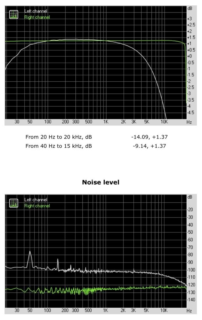
I'm beginning to think CJ has a point. I recently built an RCA BA-2 and, with slight EQing, it sounds great, but when I use RMAA to draw a frequency response plot, it starts to dip after 1k.

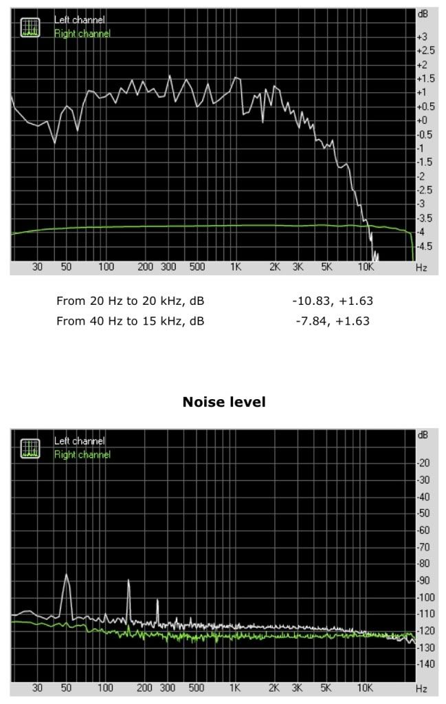
I was using my Fireface 400 to take the measurements, but unfortunately I had to send my Fireface back to Germany because the output jacks were broken.  So I've borrowed a Steinberg MR816 from work and just tried to do another analysis of my BA-2.  This time though, using the same line pad in the same settings I'm getting a very different plot - using the 816 the BA-2 line is very jagged.  What would cause this?

Here's the BA-2 frequency response measured using the Fireface 400 (the BA-2 is the left channel):
ba2cfrequencyresponse.jpg


Here's the BA-2 frequency response measured using the 816 (the BA-2 is the left channel):
ba-2mr816.jpg


Can anyone explain the discrepancies?  I should add that I did a frequency response test of the MR816 before I patched the BA-2 in and it came back perfectly flat.
 
Ah I see.  Yes I did notice I have less control over the output with the 816 vs the Fireface.  Looks like I'll have to up the pad a bit.

Thanks!
 
Back
Top