Universal Passive EQ

GroupDIY Audio Forum

Help Support GroupDIY Audio Forum:

This site may earn a commission from merchant affiliate links, including eBay, Amazon, and others.

ruffrecords

Well-known member
Joined
Nov 10, 2006
Messages
16,258
Location
Norfolk - UK
On the EZTubeMixer threads there has been some talk about providing flexibility of EQ so people can build the EQ they want, with separate switches for boost and cut if they want, rather than having to take whatever is on offer. So I had the idea of a Universal Passive EQ that would be a PCB with all the EQ components on it but none of the switches or pots. The pots and switches would connect via headers to the EQ PCB. So I have knocked up a rough schematic to get the ball rolling. This has seven switches for frequency setting, but you can of course combine some of them or miss them out completely if you wish, and has up to three inductors and a bypass switch. The seven frequency selection switches are:

S1 High Pass (non shelving) as in the Helios 69
S2 High Boost as in the regular or poor man's EQP1A
S3  Low boost as in the Helios 69 (plus a boost/cut switch)
S4 Mid boost/cut as in the 3 band Pultec
S5 Low boost as in the EQP1A
S6 High Cut as in the EQP1A
S7 Low cut (shelving)

Obviously the two Low boosts are mutually exclusive but just about all the rest should live together OK.

Comments appreciated.

Cheers

Ian
 

Attachments

  • roughschematicscaled.jpeg
    roughschematicscaled.jpeg
    134 KB · Views: 997
Hmm, interesting project. How about:

Type of EQ selectale per frequency band
Perhaps crush and blend per band or total signal
Selectable make-up stage, tube or solid state
Relay bypass per band and i/o
Stepped switches for controls like boosting / cutting / attenuatio eg

Perhaps I can imagine 2000 other options, but these came up at once
 
detonator said:
Hmm, interesting project. How about:

Type of EQ selectale per frequency band
Perhaps crush and blend per band or total signal
Selectable make-up stage, tube or solid state
Relay bypass per band and i/o
Stepped switches for controls like boosting / cutting / attenuatio eg

Perhaps I can imagine 2000 other options, but these came up at once

We are nearly there with selectable EQ type per band - shelf or bell for high boost and for low boost. Are there any other types you would like to see??
Crush and blend per band would very difficult but on total signal should be doable.
At the moment I am assuming gain make is separate from the EQ
Relay io bypass is straightforward and per band should be possible but could consume a lot of real estate - I should have mentioned I am planning on this fitting on a single Euro card
Pots are off board so stepped controls are no problem.

Cheers

Ian
 
I like the idea... I was trying to figure out a way to do cut/boost with a pot turning up or down but couldn find any way without center taped pots and custom curves... So I fell to the switch option, I would love something like this in a 51X for my mixer, maybe something simpler... Hi and low only shelving and boost cut as the mid and low band for hi...  3 pots and a couple of switchs, toggle for boost cut and maybe 2 or 3 hi/low frecs and a rotary with maybe 6 for mids.

Is there any way to do them shelving (low and hi) for boost/cut just with caps? I have 4 inductors for EQP1 I build some time ago staying there. This project may go with them.

JS
 
ruffrecords said:
On the EZTubeMixer threads there has been some talk about providing flexibility of EQ so people can build the EQ they want, with separate switches for boost and cut if they want, rather than having to take whatever is on offer. So I had the idea of a Universal Passive EQ that would be a PCB with all the EQ components on it but none of the switches or pots. The pots and switches would connect via headers to the EQ PCB. So I have knocked up a rough schematic to get the ball rolling. This has seven switches for frequency setting, but you can of course combine some of them or miss them out completely if you wish, and has up to three inductors and a bypass switch. The seven frequency selection switches are:

S1 High Pass (non shelving) as in the Helios 69
S2 High Boost as in the regular ot poor man's EQP1A
S3  Low boost as in the Helios 69 (plus a boost/cut switch)
S4 Mid boost/cut as in the 3 band Pultec
S5 Low boost as in the EQP1A
S6 High Cut as in the EQP1A
S7 Low cut (shelving)

Obviously the two Low boosts are mutually exclusive but just about all the rest should live together OK.

Comments appreciated.

Cheers

Ian

:eek:

Words cannot describe how awesome this idea is. I will be all over this thing like a fat kid on candy. You, sir, have my write-in vote for the next presidential election. ;D
 
Another incredibly cool thing about this idea:

One of the only shortcomings with the 3-band Pultec IMHO has been the inability to get useful boosts as well as cuts in the midrange. Based on my simulations the standard frequencies associated with the mid band produce rather nice cut Qs, but the boosts are far too wide to be useful (it's just the nature of the beast with that circuit as Ian pointed out). And while I do tend to cut more than I boost, at a minimum I wanted to have reasonably narrow boosts at 750Hz and 1.5kHz for guitars and basses. Even using the 2H tap the boost at 1.5kHz was still too wide, and 750Hz would obviously be even worse. Switching to a VTB9043 produces reasonable results at 1.5kHz using the 10H or 7H taps, but I would have only five frequencies to play with and I'd lose all those useful cuts. I then started considering the idea of building the EQ at 600 ohms, which would allow me to use the 2H and 1H taps for boosts and the other taps for cuts. That actually works quite nicely, but would force me to use an off-board inductor for the high band and I'd lose the convenience of having a bridging input (the latter being more of a concern than the former.)

On this new universal EQ, on the other hand, one could potentially take the low boost section (which assuming it's the same as in the Helios uses the 10H tap for all positions) and use a couple of those positions for narrow midrange boosts - or even repurpose it entirely and make it a low midrange boost/cut ala the Poshman. Or a low-upper midrange boost to complement the cuts of the standard midband and the boosts of the high band, thus giving you a full range of boosts and cuts across the entire spectrum like the MEQ5 or the Thermionic Pullet, but with an extended high end in comparison with either of those. The possibilities are nearly endless!

As long as I'm on the topic, the only thorn in my side that this approach would not solve is the minimum boost amount. The minimum cut of ~0.5dB is obviously quite reasonable, but I'm getting a minimum boost of almost 5dB in my simulations. 2dB would be optimal, and 3dB or even 4dB would be useable, but 5dB as a minimum boost is just a bit too much for my liking. I've been playing around with component values but haven't been able to find an elegant solution (and there may not be one). I don't want to derail this thread but if anybody has any suggestions please feel free to PM me.
 
Oh, and Ian, what are you thinking of as far as switching and the number of positions for each are concerned? Obviously twelve for each would be ideal, but if that's too much my vote would be for the following:

- Twelve positions for the inductive high boost, using a VTB9050 and two positions for each tap. That extends the range downward, giving you a couple of boosts at around 700-800Hz on the 2H tap and a couple around 1.5-2kHz on the 1H tap, and by spacing the positions evenly amongst the taps instead of simply adding a bunch at the high end like most extended Pultecs you get more options in the critical 1-5kHz range ala the Thermionic Pullet (there's a much greater difference between 2 and 2.5kHz than between 14 and 16kHz, for example, so expanding more in that range makes sense).

- Eight positions for the high shelf cut. Twelve would be great if possible, but eight would at least give you the six standard EQP frequencies plus a couple of extras that could be used for "air cut" bands in the 25-40kHz range (those are great for smoothing the high end without touching the presence).

- Obviously twelve positions for the mid boost/cut.

- Eight positions for the inductive low boost/cut, with the first six using the 10H tap as in the Helios and the last two using the 7H tap. That would allow for the standard Helios low boost, plus enough extension to connect the range with that of the high boost, thus giving you inductive boosts throughout the entire spectrum (I'm assuming as before that the mid band is really useful primarily for cuts). Again, twelve would be great if possible, especially with something like a Poshman in mind.

- Eight positions for the Pultec low boost and cut. The standard six and a couple more just to allow finer control over the location of the dip (IME you're generally good with the standard selection if all you're doing is boosting or cutting, but sometimes when using both together to create a dip at a certain location you find yourself wanting something in between the available selections).

- And the Helios low cut is probably good the way it is.

Just my two cents. Anyway, thanks so much for doing this! I can't wait to get my hands on these things...

 
Thanks for your inputs Tim.

A number of factors will determine the number of  switch positions we allow for each part of the EQ the ultimate one being what will fit on the PCB. Since the choice of switches is up to the individual I'll try to make as many positions available as I can on the PCB. The other main factor is the number of positions available in switches on the market. 12 is obviously common as is six and ten but I don't recall seeing any eight way switches.

You will know from the extensive posts on the subject, that the mid boost/cut mod to the poor man's EQ was something I was reluctant to undertake and is inherently compromised because of the basic circuit topology. That said, it is very similar in operation and characteristics to the Helios mid cut/boost which is said to be much liked. As you have discovered, the overall circuit impedance is the key to determining the size of inductors you need to obtain a given Q or bandwidth and the lower the circuit impedance the easier this gets which is one reason I suspect the original EQP1A works at 600 ohms. If people are going to drive this EQ from an op amp then that in itself should not be a problem but for a low cost tube mixer where you would want to perhaps drive it directly from a 10K fader your worst case source impedance is going to be 2.5K or more so you really don't want to load this with more than 10K which is exactly what the poor man's EQP1A tried to do. So if this EQ is going to be fairly universally applicable then that's probably where we need to stay. So yes, I agree with you we should aim fro a 10K bridging input impedance.

The minimum boost is more worrying and again it is due to the circuit topology. The 47K or 50K pot is operating in parallel with 4K7 in the cut position but in parallel with 47K in the boost. That is also one of the reasons I changed the recommended law from log to lin. Anyway, the solution is to use a larger value pot for the boost. This is hard to do with regular pots but if you used a switched pot you could easily have two different laws and and total resistances, one for boost and one for cut. To get to about 0.5dB minimum boost you would probably need to get the pot to 500K.

@Joaquins. I did play with a simple boost cut circuit some time ago but it is hard to get rid of interaction between the hi and lo controls. Attached is the schematic of what I was working on.

Cheers

Ian
 

Attachments

  • simplehilomidcut.png
    simplehilomidcut.png
    65.8 KB · Views: 442
Thanks Ian, nice, something like a baxandall... I think a resistor between low band and output lower the interaction.

I was talking about mid bands, I didn't say that... I have to draw it on eagle but I have to do the lib for the CT pot firts, maybe after dinner I post something.
 
I have created some updated schematics for the Universal EQ. I have divided the circuit up into its basic constituent blocks and drawn each one separately. I plan to lay them out on the PCB in this way also so that you can wire them together any way you wish. The first sheet shows:

1. Input followed by lo cut a la Helios.
2. Hi boost a la Pultec
3. Hi cut, lo boost and lo shelf a la Pultec

All very conventional so far and you can see how I have arranged them on the page much like the original sketch schematic.

http://www.ianbell.ukfsn.org/EzTubeMixer/docs/EzTubeMixer/UniversalEQ/schematicsht1.jpeg

On the second page I have tried to address the limitations of the poor man's Pultec mid boost and the inability of the Helios bass boost  to be turned completely off. The lo mid and mid hi sections shown are identical except for the inductors used. Each is basically the Helios mid boost/cut  topology which does allow the amount of boost/cut to be turned right down to zero. The idea is that these two AND the Pultec hi boost can be connected in parallel and operated at once provided their operating frequencies do not overlap. I am not 100% sure this will work although I have simulated a similar topology in the past. The three pots in parallel form the top arm of the EQ potential divider, the bottom arm being formed by the hi cut pot which will most likely be 4.7K. In the 3 band Pultec EQ this top arm is 47K  which gives a theoretical max boost.cut of 20dB and in the Helios it is 22K which gives a max boost/cut of 15dB. If we make the three pots all 100K ( a nice readily available value) the top arm resistor  becomes 33K and our max boost/cut is a reasonably 18dB.

http://www.ianbell.ukfsn.org/EzTubeMixer/docs/EzTubeMixer/UniversalEQ/schematicsht2.jpeg

The lo mid band is intended to replace the Helios bass boost and extend it upwards a bit. The mid hi is intended to replace the Pultec 3 band mid range and the Helios mid range both with some extensions upwards in frequency.

Next step is to simulate this to see if it works as expected.

Cheers

Ian
 
Yesterday an idea came to mind, schem attached, shelv (cut when set to minimun) and peak/dip as much bands as wanted with the same atten and no minimun boost or cut nor switch to boost/cut/off (off switch can be added, of course for any band)
The only thing to beat is big inductor needed for low shelving... there can be used the original pultec


Sim OK, Measured OK, tested OK and listened OK... I tested peak/dip and hi shelv simultaneous with little interaction... the pink hi shelv is with peak/dip disconnected, the other (red) is connected but zero position.

passiveEQ.jpg


Bosst and cut could be adjusted with the atten value, I just used a 14dB atten but higher values could archive higher boosts I guess and cuts with higher Z maybe...

Cheers

JS

EDIT: I forgot, the left schem would be with the center tapped/center dent pot (hard to get) but dead zero gain just in the dent, always log pot, a hevier log (A10/ A5) would make a higher boost.
 

Attachments

  • Passive.png
    Passive.png
    1.8 KB · Views: 401
I think that is a very elegant circuit.I am going to simulate it myself. Thanks for that.

Cheers

Ian

Edit: I have now simulated the htree band circuit. It is interesting in that it has the same broad mid boost and sharper mid dip as the poor man's Pultec mid mod and also as the Helios 69. Its primary advantage is a smooth transition from boost to cut and no minimum. I realised this is because I had set the pot dividers for up to 20dB cut/boost so the mid point of the pot is with 90% of the resistance at the top and 10% at the bottom. This means there is a 10:1 ratio in the time constants and Q between boost and cut.

Unfortunately this means for the lo and hi boost/cut that the boost and cut do not take place at the same frequencies. For the mid boost/cut all it means is lower Q for the boost as before. In an attempt to reduce the change in frequency for hi and lo boost/cut I changed the pot dividers to 10dB so the boost/cut range becomes only +-10dB. The means the boost/cut for hi and lo now take effect at similar frequencies. The mid cut is also nicely shaped and you can get a 20dB dip with ease. However, it flattens the top of the mid boost, This may be a great EQ shape but it sure is odd (pic attached).

I think I need to look at changing the pot divider back to 20dB but including padding resistors in the hi and low boost/cut to keep the frequencies closer together.

Cheers

Ian
 

Attachments

  • Screenshot from 2012-11-22 23:41:01.png
    Screenshot from 2012-11-22 23:41:01.png
    23.6 KB · Views: 282
ruffrecords said:
I have created some updated schematics for the Universal EQ. I have divided the circuit up into its basic constituent blocks and drawn each one separately. I plan to lay them out on the PCB in this way also so that you can wire them together any way you wish. The first sheet shows:

1. Input followed by lo cut a la Helios.
2. Hi boost a la Pultec
3. Hi cut, lo boost and lo shelf a la Pultec

All very conventional so far and you can see how I have arranged them on the page much like the original sketch schematic.

http://www.ianbell.ukfsn.org/EzTubeMixer/docs/EzTubeMixer/UniversalEQ/schematicsht1.jpeg

On the second page I have tried to address the limitations of the poor man's Pultec mid boost and the inability of the Helios bass boost  to be turned completely off. The lo mid and mid hi sections shown are identical except for the inductors used. Each is basically the Helios mid boost/cut  topology which does allow the amount of boost/cut to be turned right down to zero. The idea is that these two AND the Pultec hi boost can be connected in parallel and operated at once provided their operating frequencies do not overlap. I am not 100% sure this will work although I have simulated a similar topology in the past. The three pots in parallel form the top arm of the EQ potential divider, the bottom arm being formed by the hi cut pot which will most likely be 4.7K. In the 3 band Pultec EQ this top arm is 47K  which gives a theoretical max boost.cut of 20dB and in the Helios it is 22K which gives a max boost/cut of 15dB. If we make the three pots all 100K ( a nice readily available value) the top arm resistor  becomes 33K and our max boost/cut is a reasonably 18dB.

http://www.ianbell.ukfsn.org/EzTubeMixer/docs/EzTubeMixer/UniversalEQ/schematicsht2.jpeg

The lo mid band is intended to replace the Helios bass boost and extend it upwards a bit. The mid hi is intended to replace the Pultec 3 band mid range and the Helios mid range both with some extensions upwards in frequency.

Next step is to simulate this to see if it works as expected.

Cheers

Ian

This sounds absolutely amazing!
 
ruffrecords said:
I think that is a very elegant circuit.I am going to simulate it myself. Thanks for that.

Cheers

Ian

Edit: I have now simulated the htree band circuit. It is interesting in that it has the same broad mid boost and sharper mid dip as the poor man's Pultec mid mod and also as the Helios 69. Its primary advantage is a smooth transition from boost to cut and no minimum. I realised this is because I had set the pot dividers for up to 20dB cut/boost so the mid point of the pot is with 90% of the resistance at the top and 10% at the bottom. This means there is a 10:1 ratio in the time constants and Q between boost and cut.

Unfortunately this means for the lo and hi boost/cut that the boost and cut do not take place at the same frequencies. For the mid boost/cut all it means is lower Q for the boost as before. In an attempt to reduce the change in frequency for hi and lo boost/cut I changed the pot dividers to 10dB so the boost/cut range becomes only +-10dB. The means the boost/cut for hi and lo now take effect at similar frequencies. The mid cut is also nicely shaped and you can get a 20dB dip with ease. However, it flattens the top of the mid boost, This may be a great EQ shape but it sure is odd (pic attached).

I think I need to look at changing the pot divider back to 20dB but including padding resistors in the hi and low boost/cut to keep the frequencies closer together.

Cheers

Ian

Thanks fot the elegance thing...

First proto model (and measuraments attached) was with 8k2-1k5 atten, there is the Q thing, but also measured a small change in freq, the choice of 14dB was because of the 10K log pot I have to have a flat response about mid point. Also it shows a bigger freq shift in shelving, but I think using a low Q peak-dip in HF instead of shelving tuned around the top of the band could work as shelving for practical purposes, as seen in some LF shelvin with inductos with a big cap in series. (A P I 533 I think) Same could work with low, but again, big inductor is needed, if it's not a problem, OK. I have a couple of 1H inductors I get very cheap TX (around U$2) and work nice (tiny EI grain oriented core), same as the one used in mid band but full of wire, don't know wich freq will get with them, maybe more usefull as is in the mid band, the other I rewind for EQP1.

A second try I did was with 820Ω and 150Ω atten, but never go to a big boost because, I guess, the output Z of my sound card wich is around 150Ω if I remember well. Driving it from a low Z source it should work, but we said bridging input, so not an option here.

Anything else cames to mind at the time, I stay tuned.

JS
 
I ran some quick simulations on the Universal EQ circuit, just to get a feel for how it would work. My tests were far from comprehensive as I only tested the three inductive bands in boost mode. That said, the results were very positive.

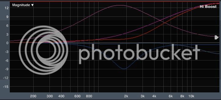
I started with two boosts maxed and the third set flat, all with their Q-pots set to their most narrow positions and with no Q-max resistor. With the bands set far enough apart that their operating frequencies would not overlap there was no noticeable interaction between them. A pleasant surprise was that, even with the bands set close together (the mid band at ~1.5k and the high band at ~3k), there was negligible frequency shift (the lower band moved downward and the upper band upward by about 40Hz each - less than a 3% shift) and the two bands retained their individual peak shapes rather than combining into one massive peak - both things that did occur with the Poor Man's mid boost. Adding the third boost at ~800Hz caused no further frequency shift in either of the other two bands, and was itself only shifted downward by about 6Hz in comparison with the position of that boost by itself. In summary, having three narrow boosts at ~800Hz, ~1.5kHz, and ~3kHz, all maxed, produced minimal interaction aside from some narrowing/distortion of their curves.

This brings up another great advantage of using the Pultec Hi-Boost/Helios Mid Boost circuit (the two are identical except for the presence of the Q pot in the Pultec circuit and the cut switch in the Helios one, and in fact Ian's drawings include the Q control in the mid and low bands as well which I think is a great idea) over the Poor Man's Mid: not only does it solve the issue with minimum boost, but it also allows for narrower curves on the boost side (and I would suspect the cut side as well, though I haven't tested it yet), which in turn allows for the mid and low bands to be located in more useful frequency ranges in conjunction with the 10k input impedance.

Of course, as we decrease the Q or reduce the amount of boost (each of which also accomplishes the other, though unlike with the MEQ5 circuit the two are not redundant and do actually produce different Q-values at the same amplitude), we see the peaks combine as expected. However, the locations of the peaks remain essentially constant and the shape of the resulting curve predictable. Not that interaction is necessarily a bad thing - the Trident A Range has significant interaction and is still considered one of the greats, albeit a bit finicky to use - but it's nice that this EQ appears to respond in a predictable manner.

One thing that I did find is that I actually preferred the response of the circuit with the three boost pots at a size of 47k rather than 100k, for a few reasons. First, the smaller pot size allows for narrower possible boosts, which again translate into lower useable frequencies for a given inductor. For instance, going with the 47k pots allows for a 1.5k boost in the mid band which very closely matches that of the Helios 1.4k at lower boost levels (which IMHO are the most important considering that one rarely boosts anything 18dB but quite frequently boosts at 0.5 to 6dB levels), whereas the 100k pots made the curves too wide even at the narrowest setting. To be more specific, at 1.5k using the 2H tap, 47k boost pot, and 10k Q pot we can get a 4dB boost with Q ranging from about 0.5 to about 1, which allows for both a nice gentle curve and a harder, more surgical peak. With the 100k boost pot, on the other hand, the narrowest 4dB boost that can be produced has a Q of <0.5, and it gets wider from there - fine if your goal for the mid band is cuts and/or very wide boosts, but not as useful if you'd like to get a nice peaky 1.4-1.6k boost for guitars from it.

The second reason is related to the first in that it is also due to the narrower curves possible with the 47k boost pots. Using the 60Hz inductive low boost with a 47k boost pot, and combining it with the 60Hz shelf cut from the Pultec, I was able to achieve curves very similar to those produced by the standard Pultec low boost/cut (with the exception of the roll-off below the 60Hz point due to the bell vs. shelf boost, which IMHO is actually an improvement as it should solve the problem Pultecs can have of the low boost sometimes getting too muddy). This combination of the Helios's inductive low boost with the Pultec's ability to dip the low-mids above the boost would be incredible useful. Unfortunately, when we go to the 100k boost pots the resulting 60Hz boost becomes too wide and we can't get those sort of curves any more.

And finally, the 47k pots give us a maximum boost of about 13dB which is still plenty for just about any conceivable purpose (APIs are limited to 12dB and I don't think anyone has ever complained about that being limiting.)

That said, I don't know what sort of other issues might present themselves by keeping the boost pots at 47k (what sort of effect that would have on input impedance, for example - calculating i/o impedance is a weak area of mine.) And I suspect that the choice of pot values would change anyway depending on which and how many bands the individual chooses to build (the idea of three 100k pots in parallel producing 33k goes away if someone only wants to build two of those bands). So it probably isn't important in terms of developing the Universal EQ, but I just thought I'd mention it in case anyone found it useful. Actually, it would probably be a good idea at some point, once the design has been finalized, to put together a small spreadsheet showing the relationship between which bands are to be built, the pot values used for those bands, and the resulting impedances and insertion losses.

Anyway, those are my preliminary findings; I hope they're of some use. Later I'll take a look at the cuts and see what sort of effect they have.
 
Thanks Tim for going to all the effort of doing those sims. I know just how easily they can soak up time.

I take your point about 47K pots instead of 100K. Of course you can get sharp boosts with 100K but you need bigger inductors and smaller capacitors and there comes a point where at some frequencies the inductors just get too big and the caps too small. 47K is probably a good compromise as it sets the top of the pot divider to 47/3K =  15k67 which is a bit lower than the Helios 22K, which explains the tighter boosts, but not so low as to threaten the bridging impedance. This gives a maximum theoretical boost of just over 12dB which is fine for most purposes.

Cheers

Ian
 
I have been thinking about the PCB layout and the best way to get the connections up to the switches. I have decided to use 0.1 inch pitch headers for this so the connections can be made with ribbon cable. I have tried to standardise on the pin numbering convention as follows:

1.  Switch positions 1..n connect to pins 1..n
2. The last two pins on the connector are for the wiper of the switch.

I have used 10 way headers for Lo Cut, Lo Boost, Hi Shelf and Lo Shelf with capacitor positions for up to 8 frequencies.

I have used 16 way headers for the Hi Boost,  LoMid Boost/Cut and MidHi Boost/Cut with capacitor positions  for up to 12 frequencies. The capacitors are paired and connected to 6 taps on an inductor. I have used the VTB 9050 footprint as it has all 6 taps present but of course you can fit other VTB series inductors with fewer taps as they will all fit this footprint.

I have used 6 way headers for the three double pole double throw toggle switches required for LoMid Boost/Cut, MidHi Boost/Cut and EQ In/Out switching.

I have created a separate set of schematics for this which you can find here:

http://www.ianbell.ukfsn.org/EzTubeMixer/docs/EzTubeMixer/UniversalEQ/PCB/

Cheers

Ian
 
ruffrecords said:
Thanks Tim for going to all the effort of doing those sims. I know just how easily they can soak up time.

No problem; I'm happy to contribute however I can.

ruffrecords said:
I have been thinking about the PCB layout and the best way to get the connections up to the switches. I have decided to use 0.1 inch pitch headers for this so the connections can be made with ribbon cable. I have tried to standardise on the pin numbering convention as follows:

1.  Switch positions 1..n connect to pins 1..n
2. The last two pins on the connector are for the wiper of the switch.

I have used 10 way headers for Lo Cut, Lo Boost, Hi Shelf and Lo Shelf with capacitor positions for up to 8 frequencies.

I have used 16 way headers for the Hi Boost,  LoMid Boost/Cut and MidHi Boost/Cut with capacitor positions  for up to 12 frequencies. The capacitors are paired and connected to 6 taps on an inductor. I have used the VTB 9050 footprint as it has all 6 taps present but of course you can fit other VTB series inductors with fewer taps as they will all fit this footprint.

I have used 6 way headers for the three double pole double throw toggle switches required for LoMid Boost/Cut, MidHi Boost/Cut and EQ In/Out switching.

I have created a separate set of schematics for this which you can find here:

http://www.ianbell.ukfsn.org/EzTubeMixer/docs/EzTubeMixer/UniversalEQ/PCB/

Cheers

Ian

This sounds great to me. Just a thought, though: as it stands you've got the three inductive bands set up for a six-tap inductor with two caps/switch positions per tap. It's a logical way to set it up, but there are just a few downsides to that approach:

1) While the VTB9043 is sufficiently different from the other Carnhill inductors to distinguish the lo-mid band from the others, the mid-hi and hi bands would likely end up quite similar to one another. Complete redundancy could be avoided by dedicating the mid band to producing good cut Qs at each position to distinguish it from the boost-only hi band, but this would not be ideal in that it would limit the flexibility of the EQ.
2) Using an inductor with fewer than six taps will also limit the number of frequencies available to 2*(number of taps).
3) Anyone wishing to build a Helios or expanded Helios would be out of luck as that requires more than two positions per tap in both the low and mid bands.

Fortunately there is a simple solution to all of these issues, and one that would greatly increase both the flexibility and universality of the EQ: rather than hard wire the inductor taps to each cap/switch position pair, leave a little space between them and have the builder jumper them together. This would allow the builder to assign the switch positions (in pairs) to whatever taps he desires. If he wants six positions dedicated to the 0.1H tap in the high band, he can have them. If he wants four positions for the 2H tap in the mid band, he can have them. If he wants to use the VTB9043 in the low band but still get twelve positions from it, he can do that as well. This approach would give the builder almost complete freedom in the selection of his frequency points and their allocation amongst the three bands, and the only cost is having to solder a handful of jumpers in each band.

There's also a bonus benefit to this approach: at the moment we're looking at a single capacitor per switch position as opposed to the two we had in the 3-band Pultec (a necessary compromise I'm sure to fit everything on the board). By using a capacitor instead of straight wire to jumper the inductor taps to the cap/switch position pairs, the builder could gain a little more flexibility in selecting his frequency points rather than being limited to what he can do with a single cap.

As always this is just me thinking out loud; feel free to agree or disagree with me as you see fit.

 
Tim, thanks once again for your excellent input. I am all in favour of flexibility. I have created a new footprint for the capacitors that allows either 5 or 7.5mm pitch capacitors to be fitted, with a single pad at one end and a double pad at the other end, giving more flexibility in capacitor choice and value. I have also used these as the links to the transformer taps with double pad at the transformer end making it easier to jumper a tap to more than one capacitor. I'll post an initial PCB layout soon.

Cheers

Ian
 

Latest posts

Back
Top