You are using an out of date browser. It may not display this or other websites correctly.
You should upgrade or use an alternative browser.
You should upgrade or use an alternative browser.
Neumann M49 Clone : D-M49c and D-M49b Tube Microphone Build Thread. (+Sample)
- Thread starter poctop
- Start date


Help Support GroupDIY Audio Forum:
This site may earn a commission from merchant affiliate
links, including eBay, Amazon, and others.
- Joined
- Jul 15, 2009
- Messages
- 2,301
Winetree said:M49 Power Supply Round transformer hook-up to main P.S.B.
Yellow & Red
Black & Orange
To P.S.B.
That is correct, the Traffo secondary output is wired in parrallele to the Main PCB,
Attachments

Had quick go added 100K to my 91K but proving difficult to tweak because I have to desolder the 100K pot to measure then do the sums...... can I connect my DMM as Ma meter and tweak for 00070A ....... Where will I need to connect meter in series ? thanks
0dbfs
Well-known member
You can temporarily connect it in series between the 100k (91k) and the plate. This should give you the accurate MA reading..
You can also calculate the current by measuring the cathode voltage and calculating current through the cathode resistor.
For instance:
Cathode = 1.6V
Rk=2k2
I=V/R
I=1.6/2200
I=0.00072727
or
0.73mA
Cheers,
jb
You can also calculate the current by measuring the cathode voltage and calculating current through the cathode resistor.
For instance:
Cathode = 1.6V
Rk=2k2
I=V/R
I=1.6/2200
I=0.00072727
or
0.73mA
Cheers,
jb
JB thanks, I was gonna ask if I could measure between plate & plate res & I thought I would try anyway
so now I have 120V B+ I tweaked the plate resistor with 47K & 100K ( will measure final plate resistance) to 0.70ma tweaked cathode resistor for -1.6V again will measure final cathode resistance plate voltage is 53.3V drop across plate resistor is 68.3V
my capsule voltage has gone right down to 42.4 not sure why....... I am using a different DMM to measure voltages now as other meter is measuring the Ma ......they both cheap meters ..... Im measuring at junction of R6 R7 both 1M so should read 60V I guess .......
As I say my circuit different slightly to what you guys are building
http://www.tab-funkenwerk.com/id89.html
Hmm both my DMM s read slightly different voltages on B+ plate & capsule voltages...... thats what I get for buying cheap ones I guess ......cathode voltage read same & milli ampage reads the same tho ........
my plate resistor ended up 103.5K and cathode resistance ended up 2279R
hope this help you builders....
One other thing I read somewhere to lower cathode resistor to 10uf for the 5840 tube I notice its 22uf on your BOM
my plate resistor ended up 103.5K and cathode resistance ended up 2279R
hope this help you builders....
One other thing I read somewhere to lower cathode resistor to 10uf for the 5840 tube I notice its 22uf on your BOM
0dbfs
Well-known member
Oliver mentioned to me to lower the cathode bypass cap to 10uf (in his ckt with a 5840) but you can try either 22(25)uf or down to 10uf to see. I think it's worth experimenting a little to see how these fine-tuning or voicing details affect performance.
Good info here!
Cheers,
jb
Good info here!
Cheers,
jb
One thing Im still not sure about is the 0.7ma thru tube & -1.6v cathode is for Ac701 tube right ? do we need to look at graphs wich I wont be able to read to find 5840 current & voltage.....
Re 25/22/10uf cathode cap that can be another experiment for me....
Also I would like to change my circuit to more like original with feedback to hear the difference that should be fun too
Re 25/22/10uf cathode cap that can be another experiment for me....
Also I would like to change my circuit to more like original with feedback to hear the difference that should be fun too
0dbfs
Well-known member
I did that w/Oliver's and CT12's (added feedback bits on one of two mic's). The output is a bit lower but it still sounds good either way ")
The current remains constant through the plate resistor, tube, and cathode resistor so you can measure it in series anywhere in that chain or via the voltage drop I=V/R maths.
Cheers,
jb
The current remains constant through the plate resistor, tube, and cathode resistor so you can measure it in series anywhere in that chain or via the voltage drop I=V/R maths.
Cheers,
jb
micaddict
Well-known member
Yep, plenty similarities there. And of course both originally had the AC701 tube.
Matador designed the C12 PCB and next will be the Ela M251 twist (perhaps even on the same board). Well, the Ela M251E (export version) actually, since it will be for the 6072a tube. I suggested he'd do a subminiature tube (original, non -E) version, too, that could work with Dany's PSU.
Matador designed the C12 PCB and next will be the Ela M251 twist (perhaps even on the same board). Well, the Ela M251E (export version) actually, since it will be for the 6072a tube. I suggested he'd do a subminiature tube (original, non -E) version, too, that could work with Dany's PSU.
Looking at this build I'm a bit unclear on a couple of things...
Where is the switch for the capacitor across the capsule? (S2). It seems like you leave it unconnected on your build...and what does this cap do?
Also, what happens with pin 8? (calibration input on the Neumann schematic)
Thanks,
Paul
Where is the switch for the capacitor across the capsule? (S2). It seems like you leave it unconnected on your build...and what does this cap do?
Also, what happens with pin 8? (calibration input on the Neumann schematic)
Thanks,
Paul
- Joined
- Jul 15, 2009
- Messages
- 2,301
pH said:Looking at this build I'm a bit unclear on a couple of things...
Where is the switch for the capacitor across the capsule? (S2). It seems like you leave it unconnected on your build...and what does this cap do?
Also, what happens with pin 8? (calibration input on the Neumann schematic)
Thanks,
Paul
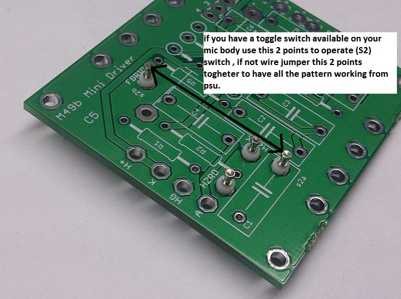
Thanks For the Note Pip , it has been anticipated as they are one leg of the cap that is mounted on a teflon turret as depicted in the picture,
as for the pin 8 it is also as the original schematic on the pcb, it is used to inject a signal and calibrate later C4, C4 is a balancing capacitor for the low end and high end , it is usually 8 pf but can be tweaked it can range from 8-12 pf IIRC.
Hope this helps, I am adding it to the build thread at the moment.
All M49 models after 1957 had a “cardioid only” switch built in, to achieve a 4dB s/n improvement [as compared to setting the pattern] remotely, from the power supply.
Note: To Operate S2 Cardiod only Switch
Best,
Dan,
- Joined
- Jul 15, 2009
- Messages
- 2,301
Adjusting your PsU for AC701K tube operation using the PSU pcb of this project.
So For B+ the idea at this point is to stick the 150K resistor between pin 5-7 of your Psu connector and adjust the voltage to 116V on the psu,
Make sure you actually read a voltage drop acrross this resistor for 116V , so at 116V/150K = 0.77ma at 116V the neumann spec,
in theory you would need here a 0.25W resistor cause 0.77ma *116V = about 0.1W
Same thing for the heater 4V at 100ma this would be the equivalent of plugging a 40 ohm resistor between pin 4-7
So 4V/40ohm = 100ma , this way you can ball park adjust the psu before you connect it to the mic,
in theory you would need here a 0.5W resistor cause 100ma *4V = about 0.4 W if you make the adjustment pretty quick it should not overheat too much at 0.25W,
once the mic is connected fine tune the adjustments while the mic is warming up and the psu also.
Hope this helps,
BEst,
DAn,
bernbrue
Well-known member

- Joined
- Jul 15, 2009
- Messages
- 2,301
bernbrue said:Hi,
pictures of our work in progress.
regards
Bernd & Reiner
Nice doing Bernd and Reiner , I hope everything is going well with your prototype version PCB,
Will stay tune and prepare some popcorn as well,
Best,
Dan,
Spencerleehorton
Well-known member
Hi Dany,
so this
Adjusting your PsU for AC701K tube operation using the PSU pcb of this project.
So For B+ the idea at this point is to stick the 150K resistor between pin 5-7 of your Psu connector and adjust the voltage to 116V on the psu,
Make sure you actually read a voltage drop acrross this resistor for 116V , so at 116V/150K = 0.77ma at 116V the neumann spec,
in theory you would need here a 0.25W resistor cause 0.77ma *116V = about 0.1W
Same thing for the heater 4V at 100ma this would be the equivalent of plugging a 40 ohm resistor between pin 4-7
So 4V/40ohm = 100ma , this way you can ball park adjust the psu before you connect it to the mic,
in theory you would need here a 0.5W resistor cause 100ma *4V = about 0.4 W if you make the adjustment pretty quick it should not overheat too much at 0.25W,
once the mic is connected fine tune the adjustments while the mic is warming up and the psu also.
Hope this helps,
BEst,
DAn,
will this setup work for the M269c as well?
regards
Spence.
p.s dont know if ive got a 40ohm resistor!!!
- Joined
- Jul 15, 2009
- Messages
- 2,301
will this setup work for the M269c as well?
the principle is the same but the calculation number diefferent but the same results the adjusted voltage will be diefferent for this tube only for the heater
For the 5840 tube ,
B+ is a 120V at 0.8ma approximately so , U= RI then U/I = R = 150K ish resistor will act as a loading,
for the Heater , 150ma at 6V ------> 40 ohm ish,
Wattage = P=VI ------> for B+ 120V*0.0008A = 0.1W
-------> for the Heater 6V*.150A = 0.9W = 1W
hope this helps,
Best,
Dan,
Spencerleehorton
Well-known member
HI all,
need some help a. getting my brain around all this!!!! b. getting the correct voltages on the cathode.
First of all im using the 5840W tube.
PSU seems to check out with the correct voltages and everything seems to work well without blowing up!!!!
Once the mic is plugged in and after a minute to heat up im getting the following voltages:
PSU at pint 4 = 6.5v
PSU at pin 5 = 120v
PSU at pin 6 = 56.4v
at H+ on mic = 6.3v
at K on mic = 1.0v
at HG on mic = 0v
at A on mic = 39.5v
I cant seem to get the cathode up any higher, Dany says it should be 1.6v, but other than crank the voltage on the psu up to raise the cathode I dont know what else i can do!!!!
I have cleaned the pcb with 99% IA so it is clean, but is there i can back trace to getting the correct voltages?
or can anyone spot my mistake?
regards
Spence.
0dbfs
Well-known member
Try a small 5k tweaker in the Rk position and tweak till you've got between 1.6V and 1.8V on the cathode.. Then swap a resistor in that matches the value.. Or try some different value R's in the Rk around that 2k2 range..... you know, 1k, 2k, 2k5, 3k, etc.....
If you have a different tube try that too and you may want to tweak the heater down to 5.7V or so.
Look forward to hearing your impressions on this and which capsules/trafo's you used.
Cheers,
jb
If you have a different tube try that too and you may want to tweak the heater down to 5.7V or so.
Look forward to hearing your impressions on this and which capsules/trafo's you used.
Cheers,
jb
Similar threads
- Replies
- 19
- Views
- 8K
- Replies
- 23
- Views
- 9K
- Replies
- 25
- Views
- 10K