Neumann M49 Clone : D-M49c and D-M49b Tube Microphone Build Thread. (+Sample)

GroupDIY Audio Forum

Help Support GroupDIY Audio Forum:

This site may earn a commission from merchant affiliate links, including eBay, Amazon, and others.
Hi,

Ah so if i use lower resistors this should give me higher cathode voltage as i understand it?
Im using the RK47 capsule and a sowter 9610 at the moment but have a few other choices transformer wise.
will give it some tweaks tomorrow and see if i can get a higher cathode voltage.

regards

Spence.
 
Higher Rk makes higher voltage @ K..

That is a string of resistors from B+ to GND with the tube being a "variable-resistor" depending on operating points. Like this:

B+ -> Rp -> anode-5840-cathode -> Rk -> GND

So, measuring a Voltage at each node is exactly the same as measuring at points in a voltage divider / resistor string.

B+ is 120V.. Across a 100k Rp then 39V @ anode.... Means we drop 81 volts across the 100k or in other words, 0.81ma of current from B+ through tube anode/cathode to GND...

2k2 Rk dropping 1V shows .45ma though. Do you have a 200k plate resistor?

M49B or C?

Cheers,
jb
 
Hi,

its a M49c, i have tried it with a 5k pot at R7 but will try a 2k2 to see if i can get higher cathode.
where are you meaning to use the 200k? i dont see that on the m49c schematic?

regards

Spence.
 
Hi,

Have tried as you've suggested changing R7, and ive tried 560ohm right through to 2.2M and i get 1.1v with 2.2M!!!
Dont know what you mean about the 200k resistor as this is only in the m49b version, i am doing the M49c version.
This is really buggin me now!!!

regards
Spence.
 
Hi,

Just put together the puck version of the M49c and exactly the same thing happens with the Cathode low voltage? 0.8v
The tube im using is a Philips 5840W and i have changed it for another one and get same result!!
only one change i have made from before and used a 470pf polystyrene rather than a 560pf.
Everything else is correct as per schematic!!!
Help its driving me insain!!!

regards

Spence.
 
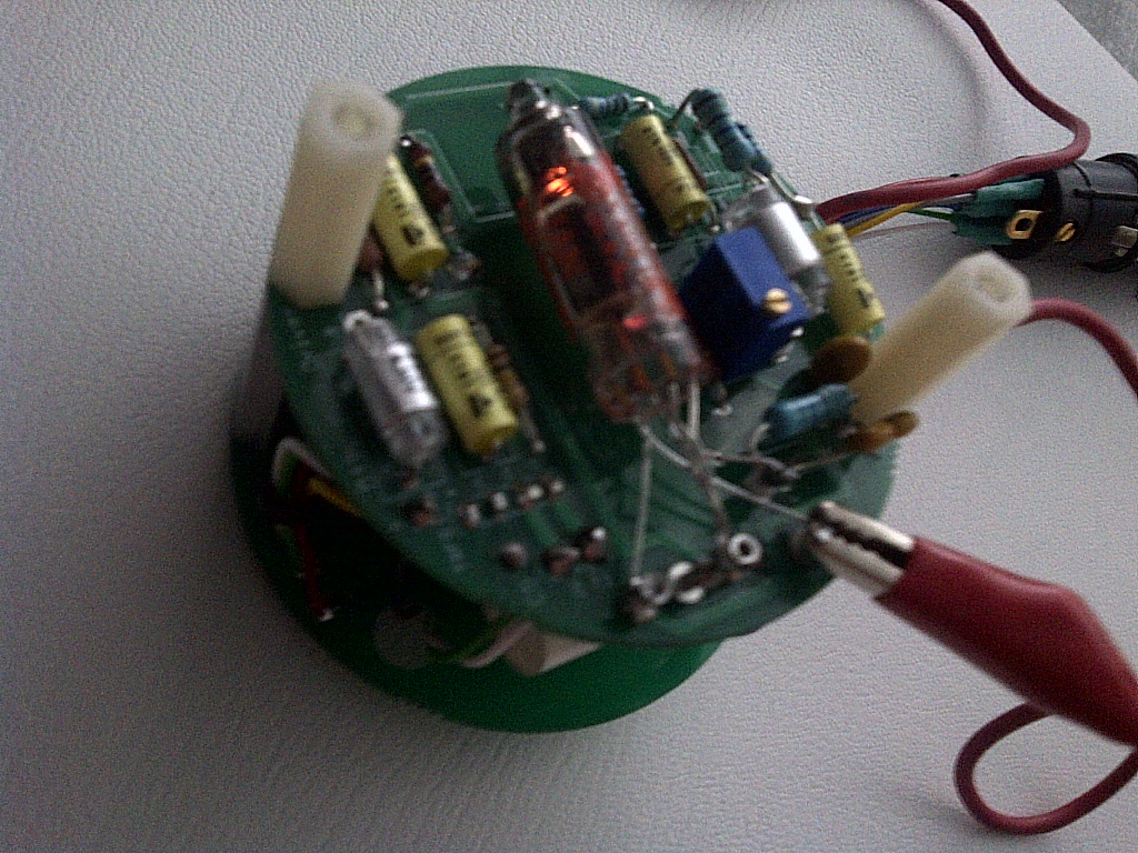
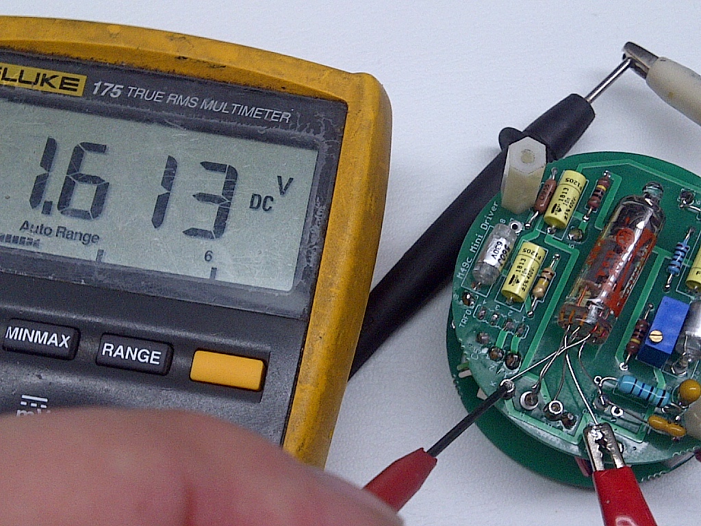
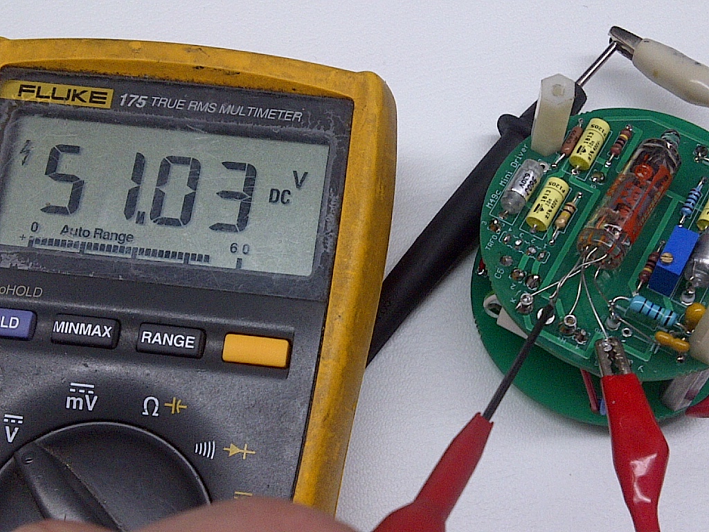
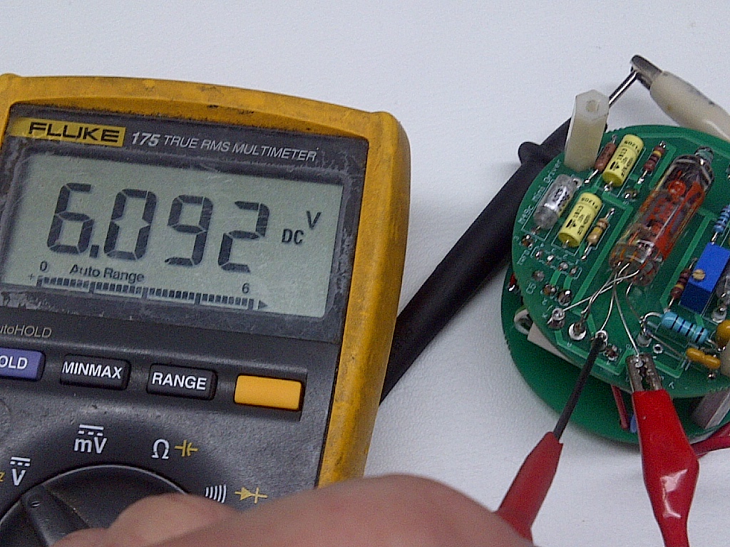
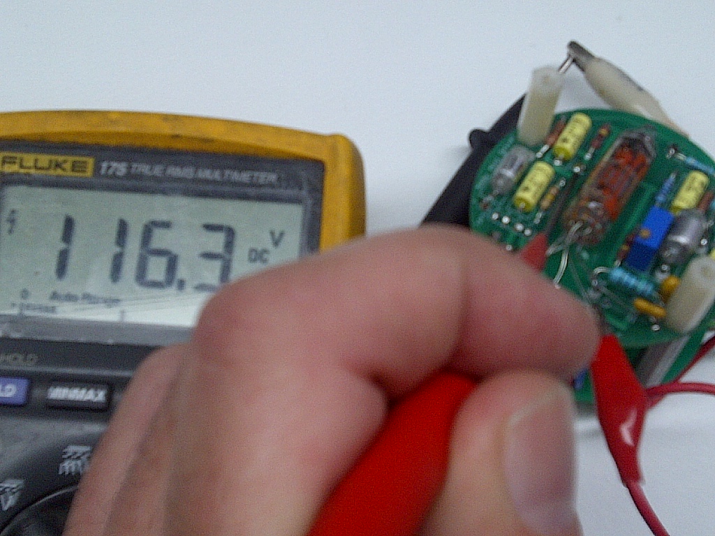
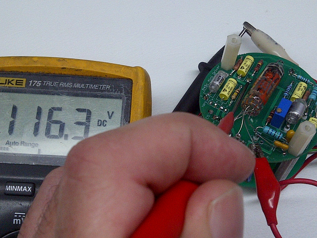
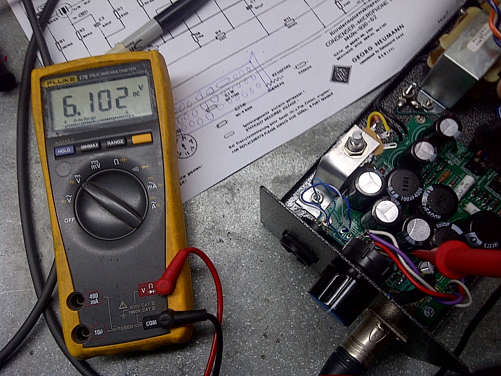
Hope checking those picture will help finding your issue , this is what i have here , works like a charm  :)

What is the ratio of your transformer ?  .....  Where do you actually Measure the Kathode voltage against what reference ?

B+ was readjusted to 120V afterwards hence the 50V  on the plate wich is about 4-5V higher than the cal point at (116V-120) = 50-4= 46Vplate.

58d1402a05a9b.jpg


58d1402a05aa8.jpg


58d1402a05ab9.jpg


58d1402a05aca.jpg


58d1402a05adb.jpg


58d1402a05ae8.jpg


7_7.jpg


58d0281993d65.jpg


Hi Dany,

the transformer is a 9610 sowter which is 10:1 ratio

http://www.sowter.co.uk/specs/9610.htm

dont really understand what you saying about:

B+ was readjusted to 120V afterwards hence the 50V  on the plate wich is about 4-5V higher than the cal point at (116V-120) = 50-4= 46Vplate

could you be more specific in laymens terms please.

I am measuring it with black multi meter lead on earth and using other red lead to check voltages with multi meter set to V- 200.

Im more confused now than ever!!! perhaps im having a bad week!!!

regards

Spence.
 
Kit in Stock,

http://www.groupdiy.com/index.php?topic=49675.480
Best,
Dan,
 
important Information For All M49 and 269c builder

the psu pinout  connection shows that pin 3 is the cable shield lift channel with the jumper that should be by default installed on the psu , unless a specific cableshield scheme is used  and that pin 7 is the Audio Ground ,

on the M49 Mic pcb as per the original numbering the pin 7 is actually the shield from chassis and the pin 3 is the audio ground ,
since the 2 points are linked on the pcb they are basically the same but special attention must be taken to actually take into account for this properly grounding the mic and cableshield as the number are reversed on the mic end ,

take special attention to ground loop while grounding the shield of the mic cable ,


the same PSU can be used for the M269C build but note that the difference is that pin 3 is the calibration input on the mic pcb not the shield ,
there is a pad on the 269 pcb labeled Cal on the mic pcb. Always have the original schematic of the mic when building as all the numbering on the mic pcb always follow the original numbering on the schematic as opposed to the psu that will always stay te same for both mics 49bc-269c ,
the remote pattern on the M269c is like the original as well that is you have to switch on the mic pattern and then on the psu to get the poper pattern , ( see schematic)  the use of a linear pot can be used in both configuration for the pattern ,

I went to update the PsU schematic with proper labeling of the output pin of the psu and also did this little table that will help explain

Best,
Dan,

Cabling connection From PsU https://cdn.groupbuilder.com/groupdiy/u/39511/58d0281993e71.jpg

Side Note: For those having a polarity that is reversed for a known or unknow reason , remember that you can swap the wire inside the psu at the xlr output connector swapping wire pin 2 and wire pin 3 will reverse the polarity of the ouput.


Hello Dan,

Terry Setter here.  I design tube mics for Chameleon Labs, Cascade Mics, and custom builds.  I've been studying the M49 series of designs and it appears that you've already gotten WAY into them.  Could you characterize the sonic difference between the M49b and M49c bias schemes?  I read your post that said you were very happy with the sound of the M49b model you had built, but I'd LOVE more specific comments about what is different between them. 

I realize that Neumann made changes to lower noise and raise RF rejection, but there are always sonic costs, etc., and I know of people who are having their M49c models stripped of the feedback circuitry.  I don't know of anyone who has reverted the bias system (and this might be due to sloppy heater voltage smoothing).

Any comments about the differences between these two mic models would be MOST appreciated.

Regards,

Terry
 
terry setter said:
Hello Dan,

Terry Setter here.  I design tube mics for Chameleon Labs, Cascade Mics, and custom builds.  I've been studying the M49 series of designs and it appears that you've already gotten WAY into them.  Could you characterize the sonic difference between the M49b and M49c bias schemes?  I read your post that said you were very happy with the sound of the M49b model you had built, but I'd LOVE more specific comments about what is different between them. 

I realize that Neumann made changes to lower noise and raise RF rejection, but there are always sonic costs, etc., and I know of people who are having their M49c models stripped of the feedback circuitry.  I don't know of anyone who has reverted the bias system (and this might be due to sloppy heater voltage smoothing).

Any comments about the differences between these two mic models would be MOST appreciated.

Regards,

Terry

Hi Terry , i have not been able so far to have a (b) and (c) built up at the same time , the first one was a prototype in a different mic body , and the second one is about to be built in the proper mic body here: http://groupdiy.com/index.php?topic=52563.0
i will be more than happy when those are finalized to let you knowhow it feels

as a primer i have also found this that explains the difference between the 2.

http://repforums.prosoundweb.com/index.php?topic=5534.0

Stay tuned,

Best,
dAn,
 
Terry, good to see you around these parts. The "C's" (original) seem to generally be "preferred" by users out in the field. There are a couple feedback paths and filters in there. The b has all that but uses the different bias scheme.

I've been so busy I haven't had time to finish these yet but when I do I'm going to stuff both the b and c boards so I can swap accordingly. Not an "in the field" swap but if I've got an iron...

Cheers,
Jonathan
 
Hi Terry,

You can read about cathode bias versus fixed here:

http://www.foxaudioresearch.ca/the12.htm

According to the Brian Fox on his site: "…the fixed grid bias voltage  ...removes the low frequency response limits and phase distortions that occurr when you use the resistor/capacitor network in the more commonly used "cathode bias" configuration. And because the cathode is connected directly to ground, fixed bias also maximizes the gain of the tube."

I've experimented with this quite a bit. To my ear, bass response is better with fixed bias, and the microphone just sounds better. Of course, the Tele ELA M 251 has a cathode bias and it is considered a classic  …but when I changed my "clone" to fixed bias I liked it even better. It's all subjective, of course….

The downside is that you need a very clean power supply, so it might be more expensive to make a fixed bias mic and do it right.
 
The "C's" (original) seem to generally be "preferred" by users out in the field.

Not so sure about that one. Depends on the purpose.
Also, there's the M7 vs. K47/49 capsule to take into account.

Of course, addicts want 'em all.  :p

 
bioman666 said:
Hi everyone !

I can't find R1 and R10 on the M49b BOM... Is it supposed to be sourced somewhere else ?

Hugo.

only C1 and C6 are sourced or ordered on the online store as Styro cap kit for D-M49B and C 

Both the 100K and the 150M are in the BOM here :

M49 C or B Mic Parts
http://www.mouser.com/ProjectManager/ProjectDetail.aspx?AccessID=f556c18411

Let me know if you have an issue with the BOM
Best,
Dan,
 
Hi Dan,

Ok for the 150 M, I misread the MOX component.

But as for the 100 k, I get confused. The BOM says it is both R5 and R9, but on the schematics, these resistors are supposed to be 1 M and 150 M... :eek:

Am I reading it wrong ?
 
bioman666 said:
Hi Dan,

Ok for the 150 M, I misread the MOX component.

But as for the 100 k, I get confused. The BOM says it is both R5 and R9, but on the schematics, these resistors are supposed to be 1 M and 150 M... :eek:

Am I reading it wrong ?

Please do not refer to the Customer part number in the mouser BOM cause the part number is associated with other projects,
i will remove them all when i have a little time to avoid further confusion ,
Best,
DAN,
 

Latest posts

Back
Top