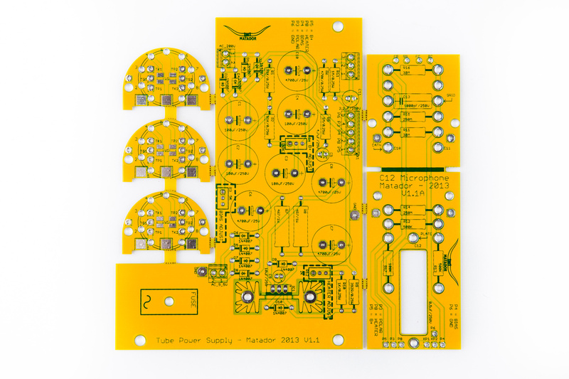
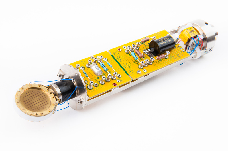
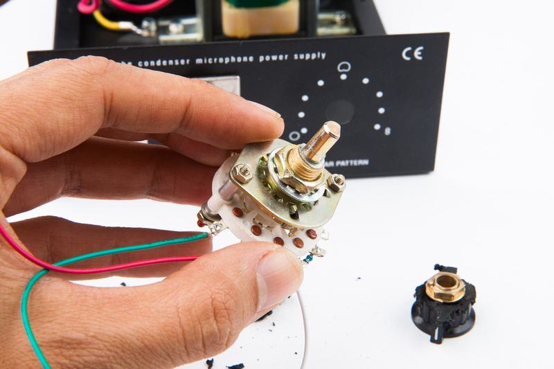
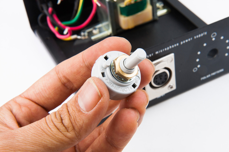
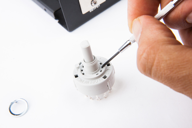
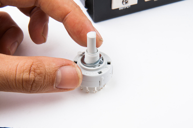
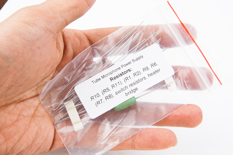
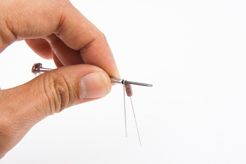
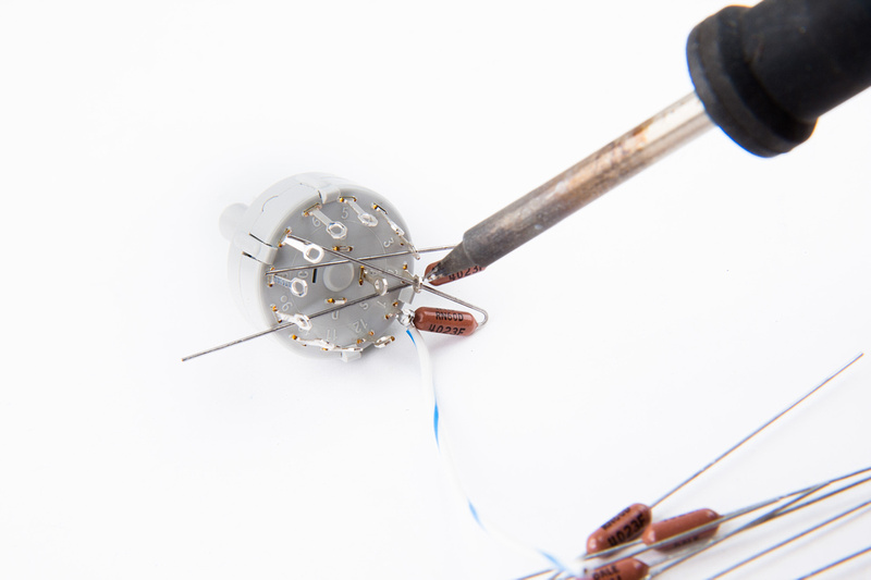
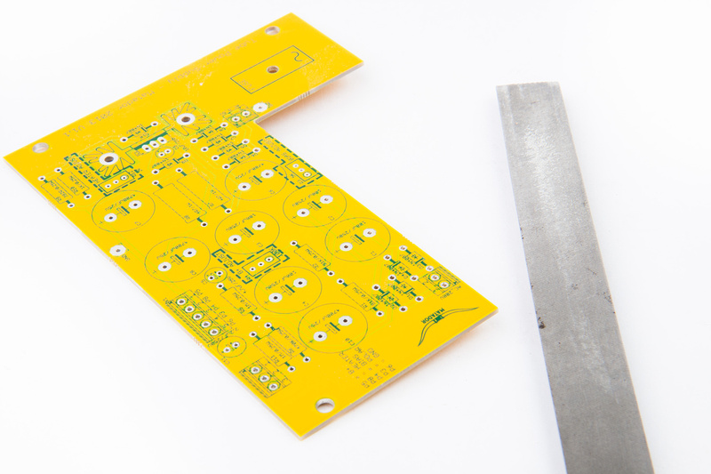
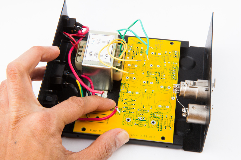
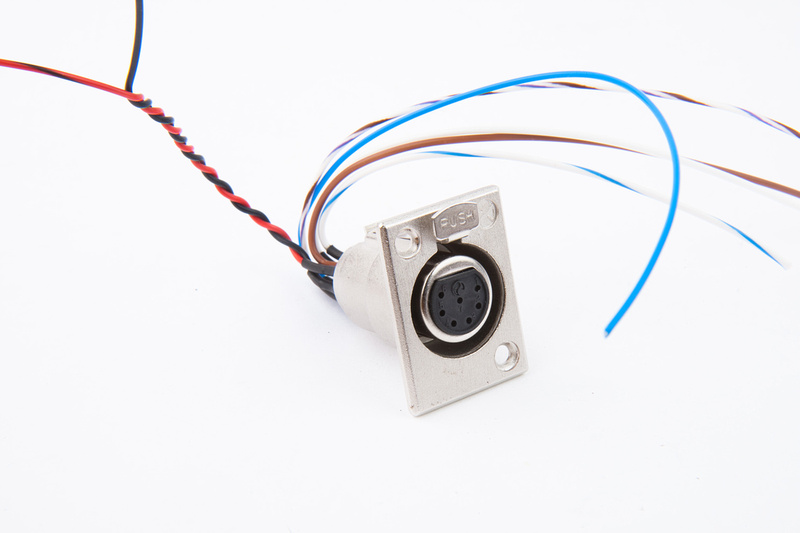
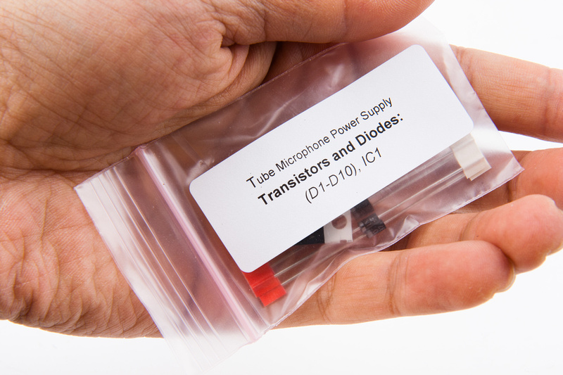
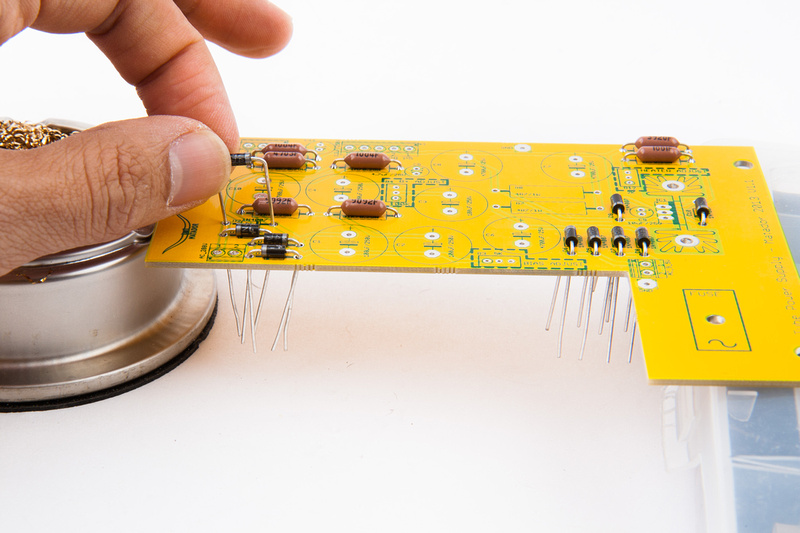
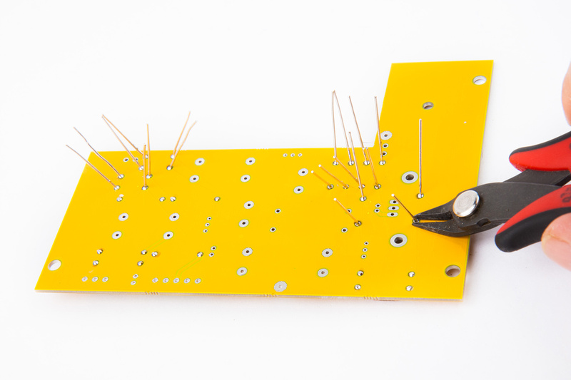
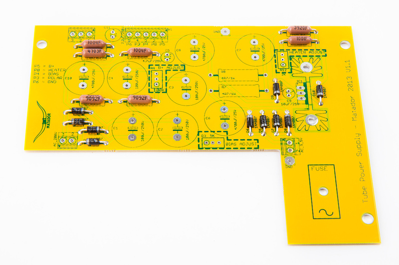
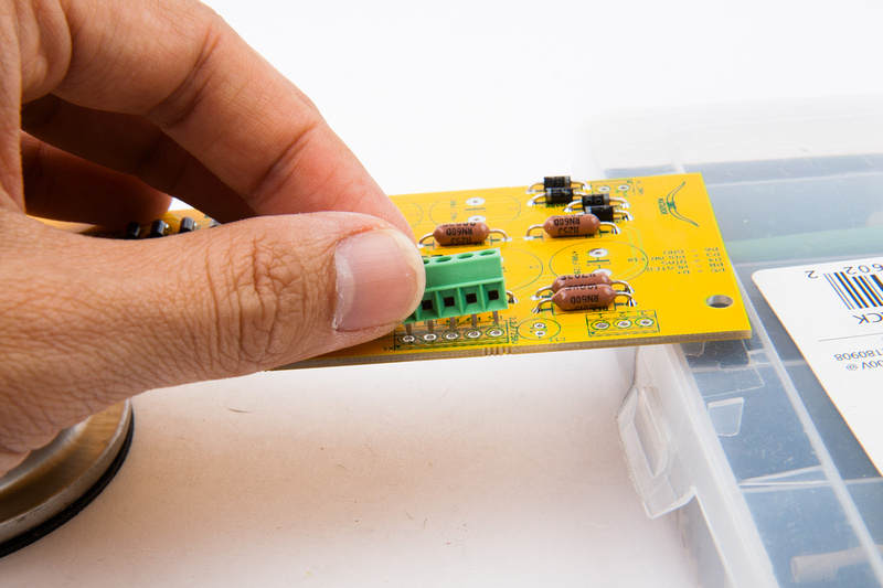
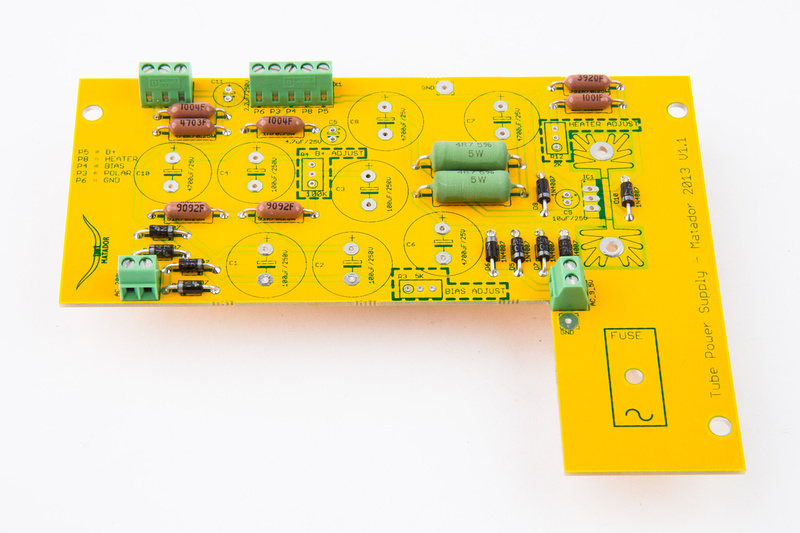
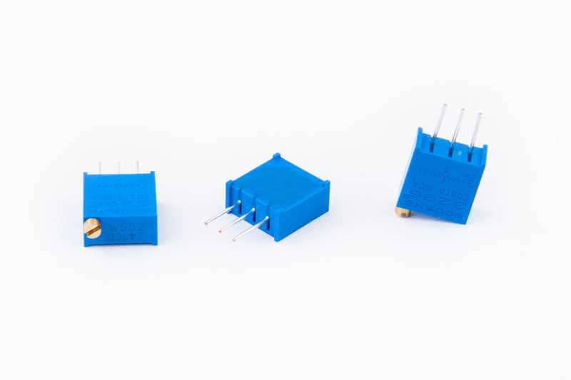
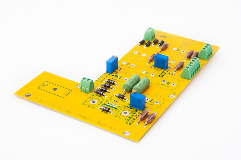
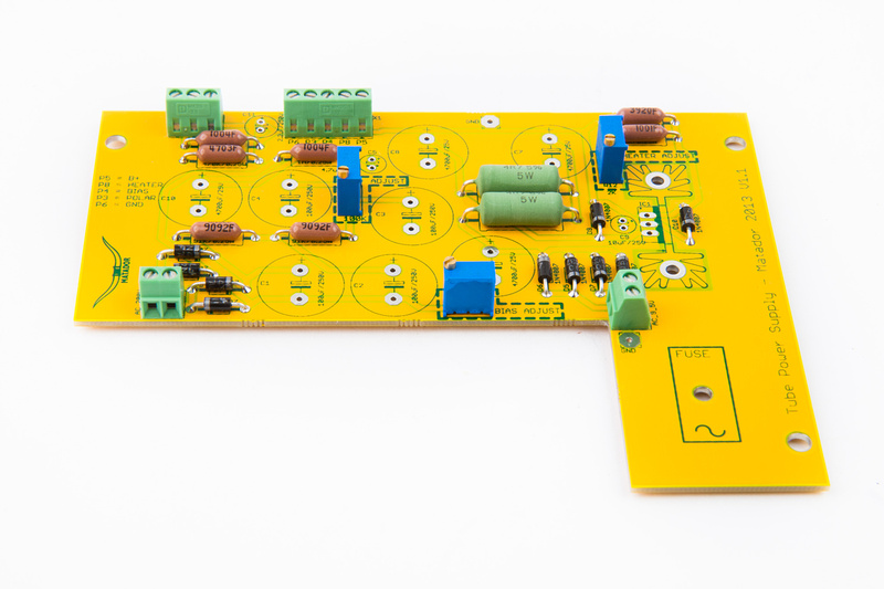
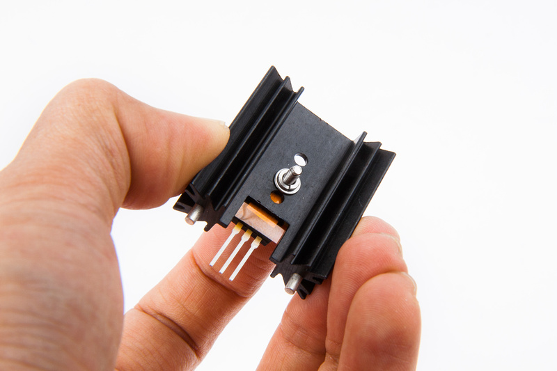
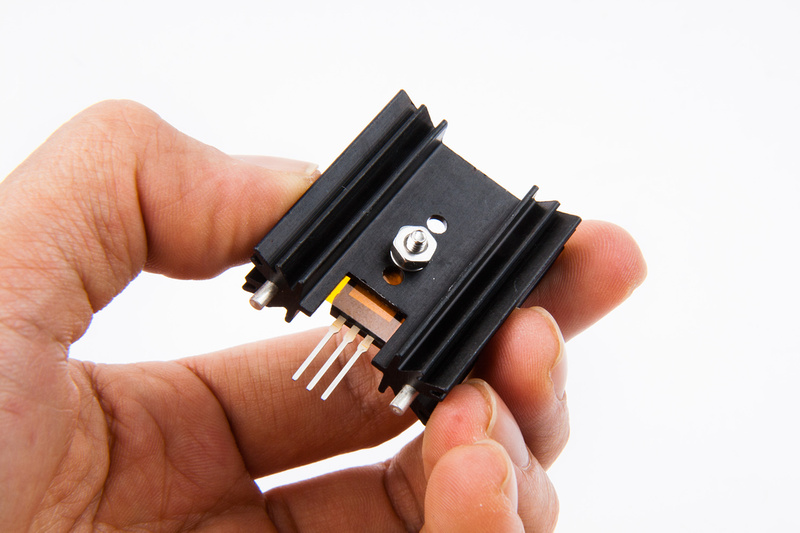
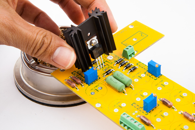
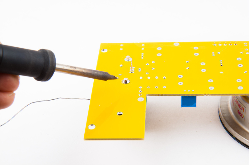
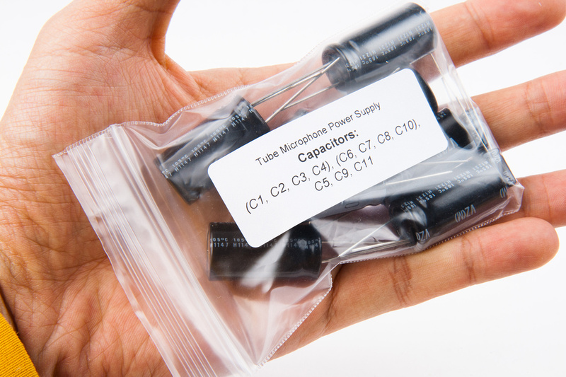
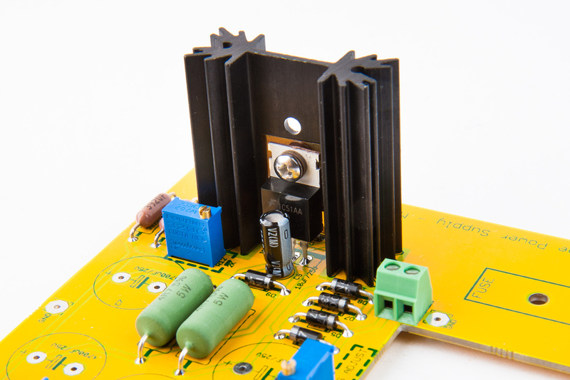
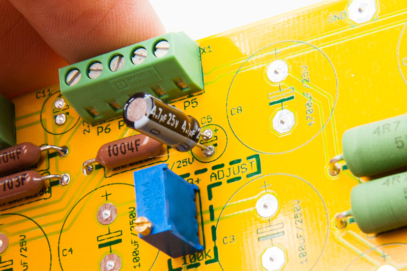
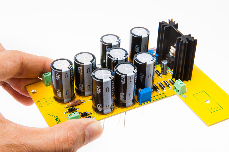
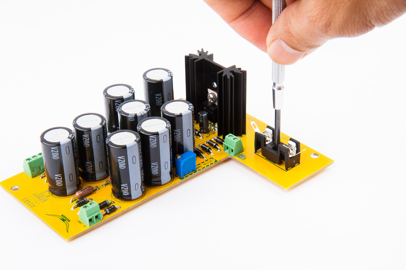
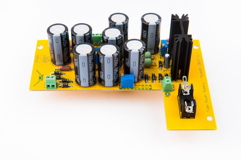
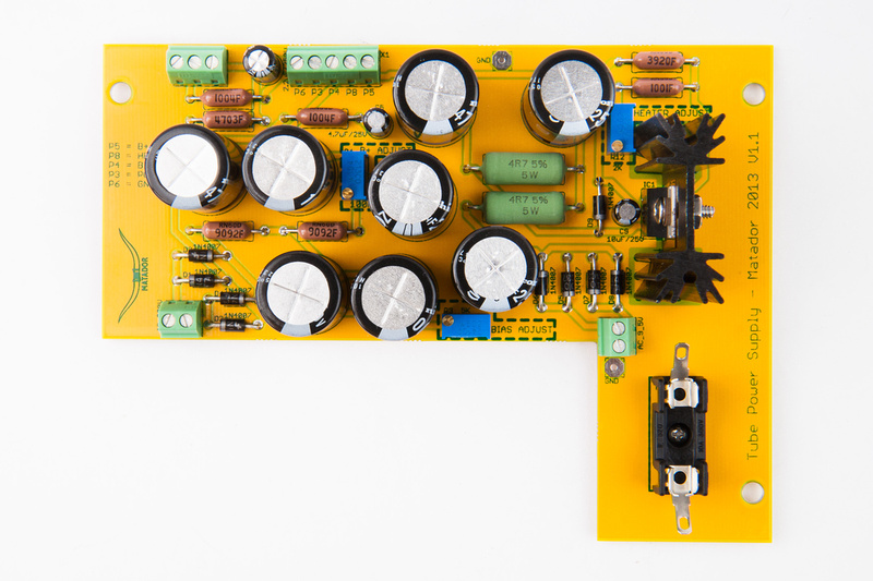
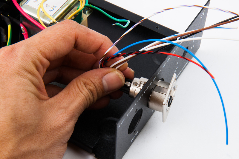
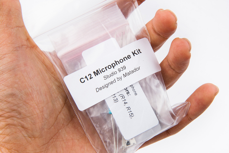
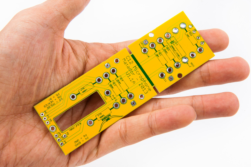
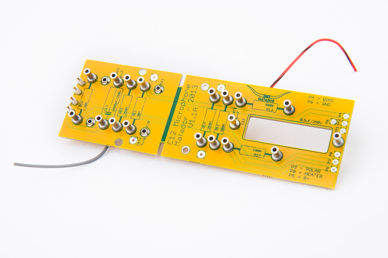
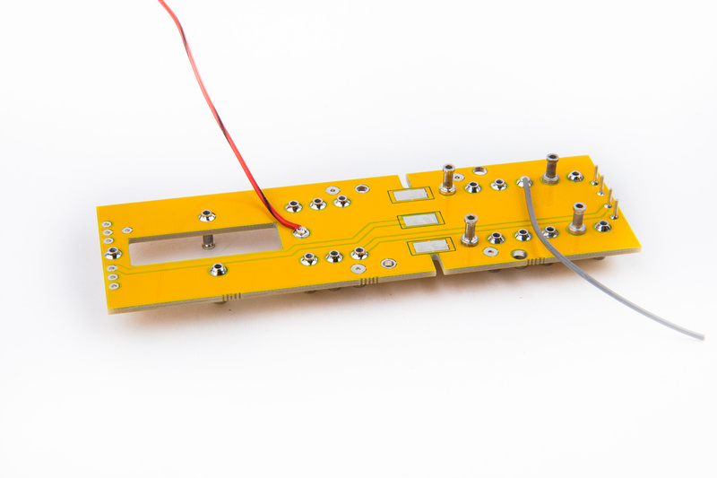
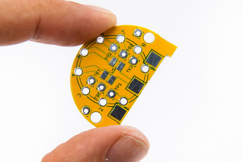
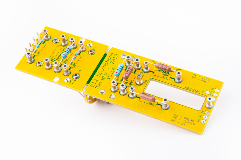
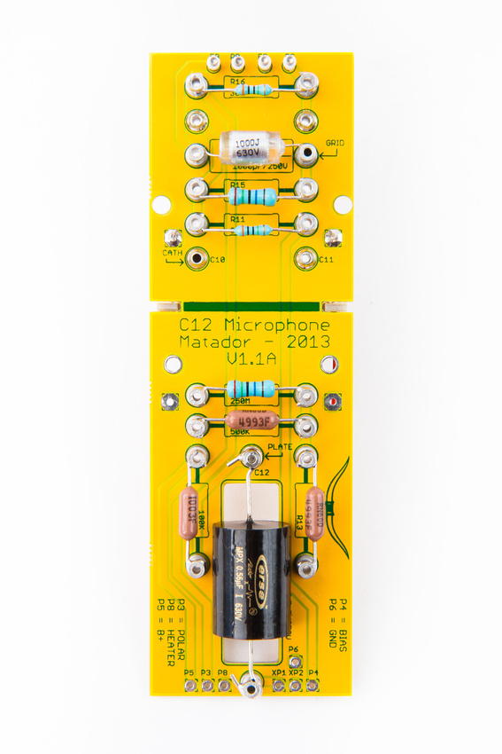
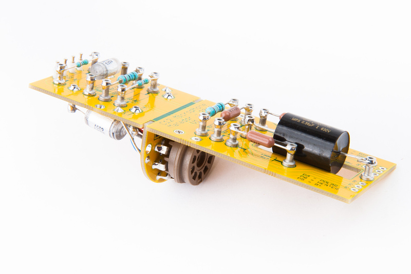
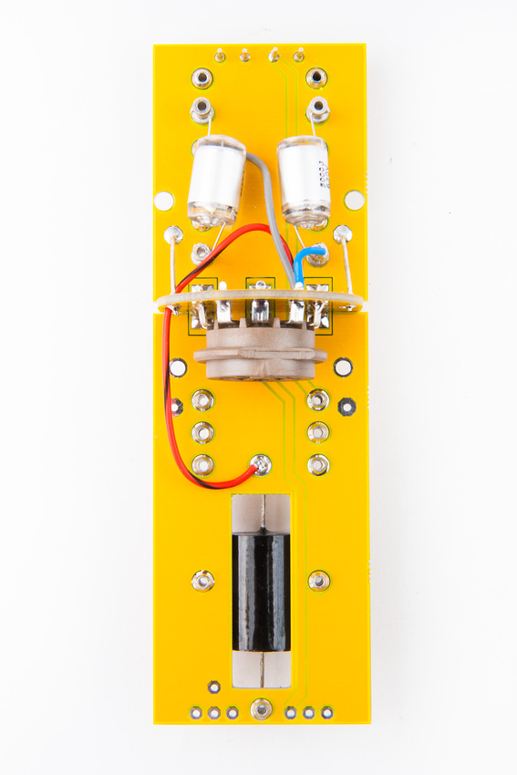
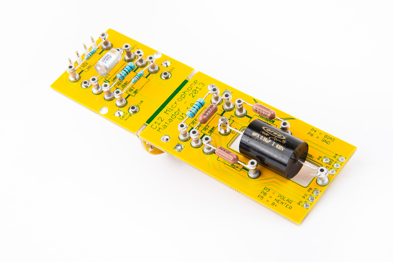
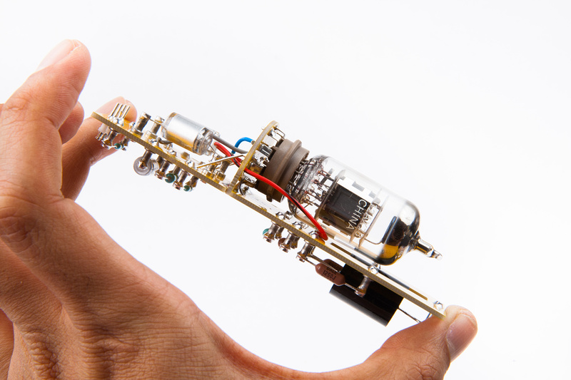
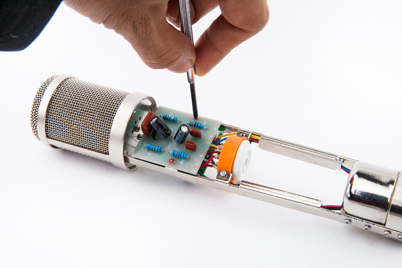
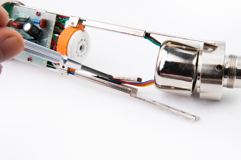
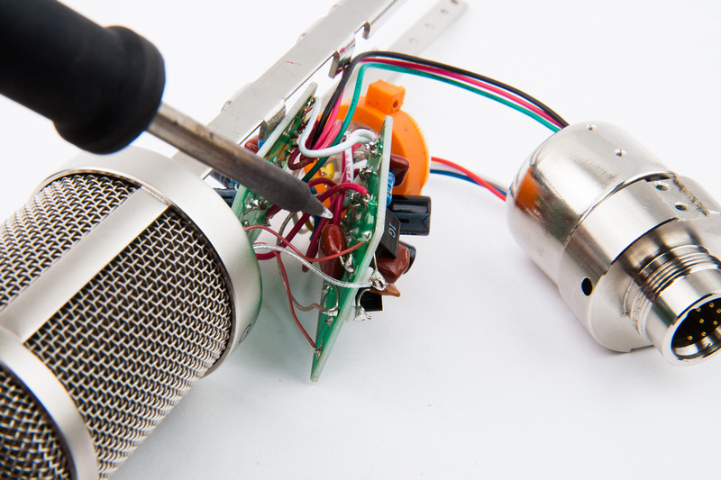
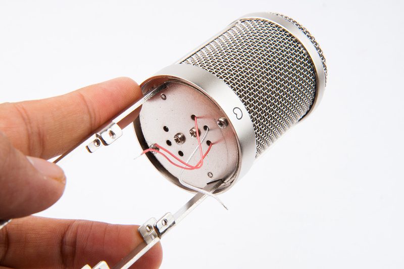
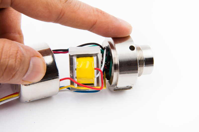
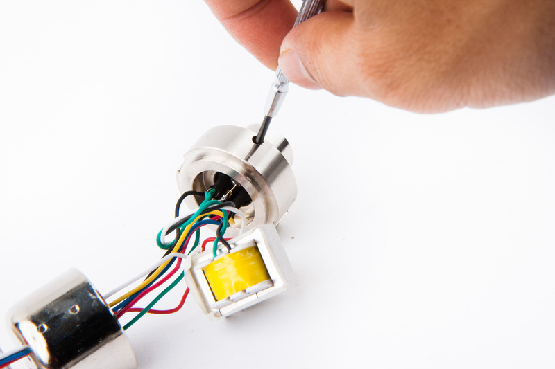
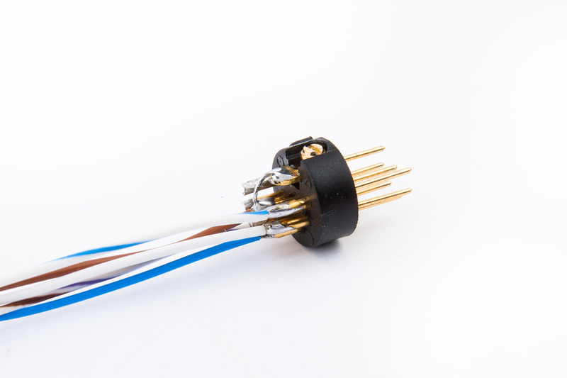
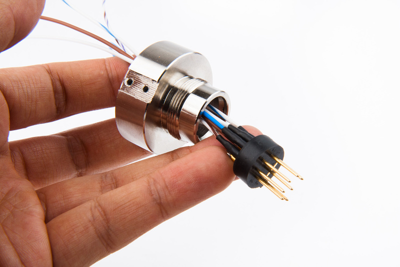
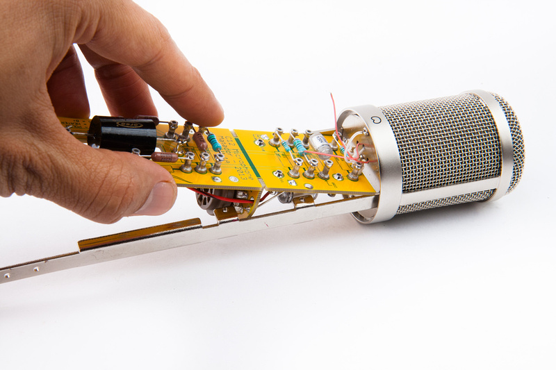
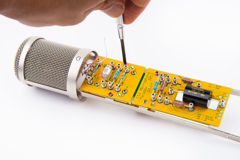
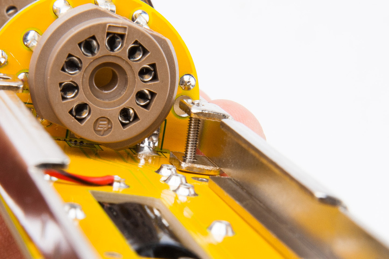
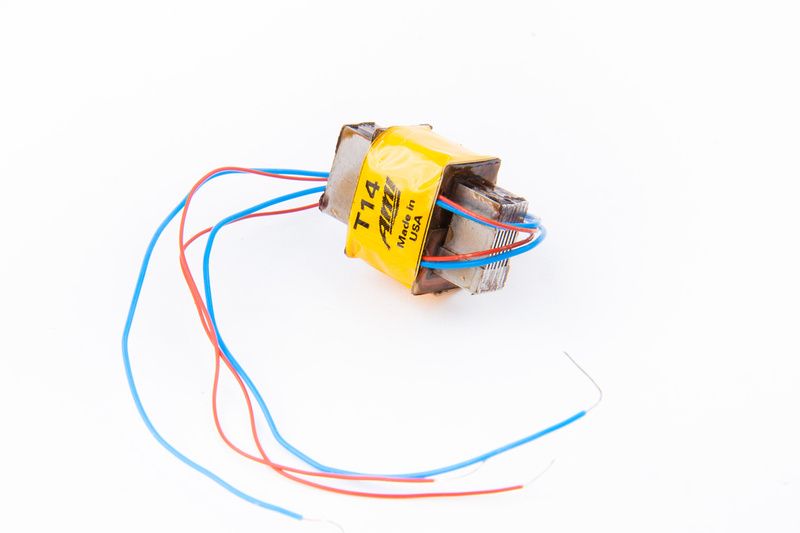
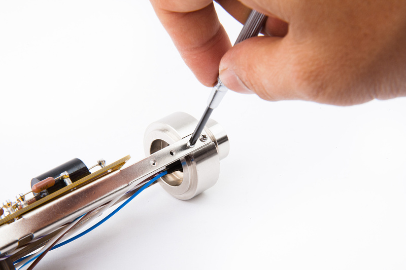
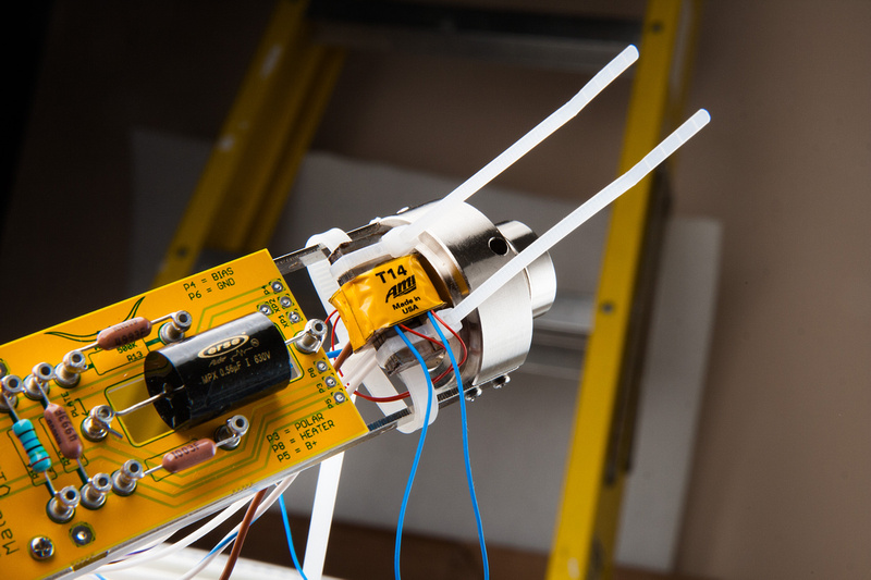
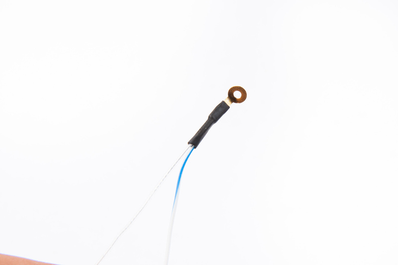
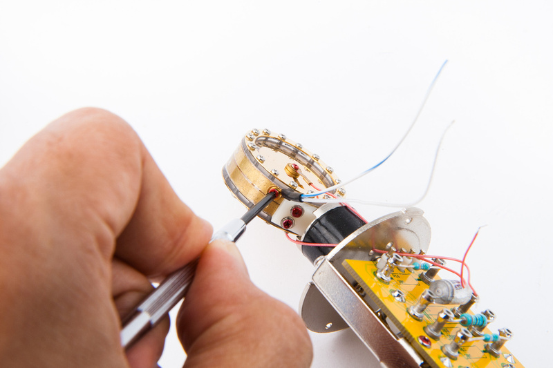
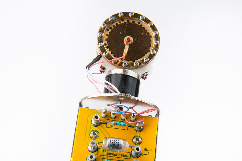
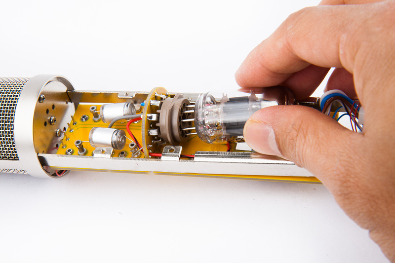
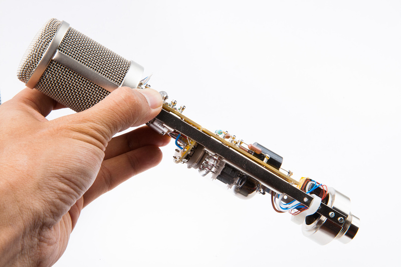
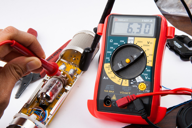
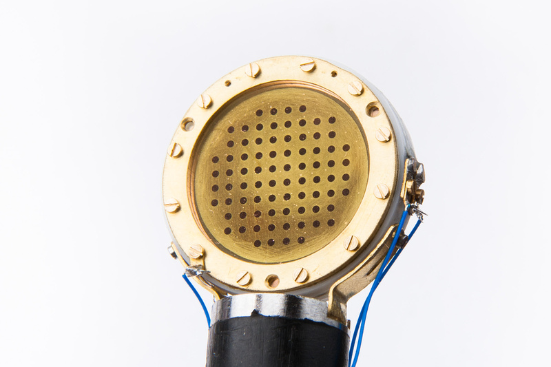
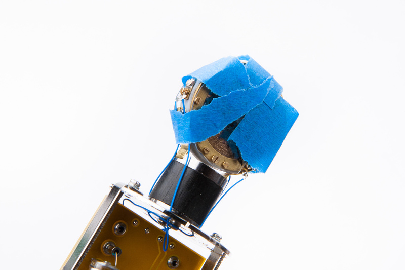
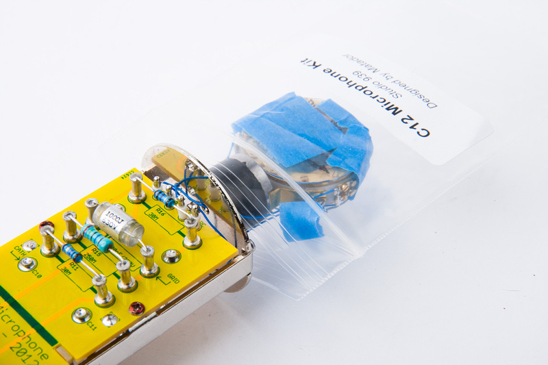
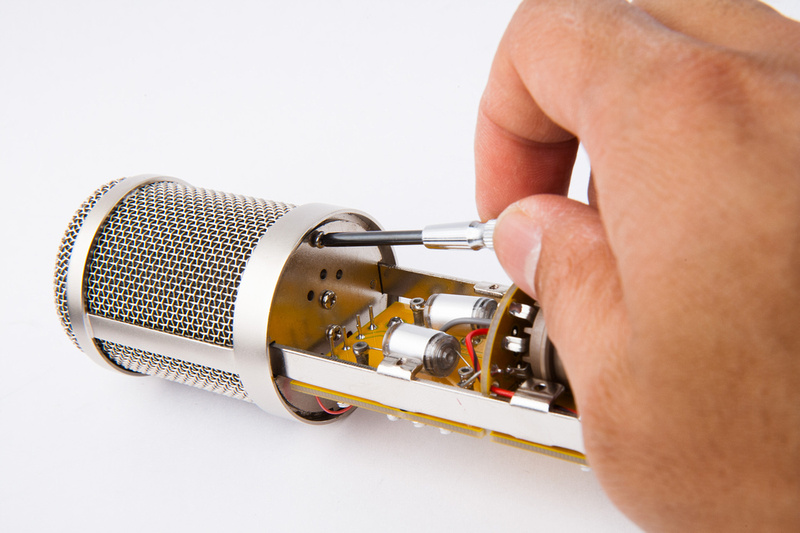
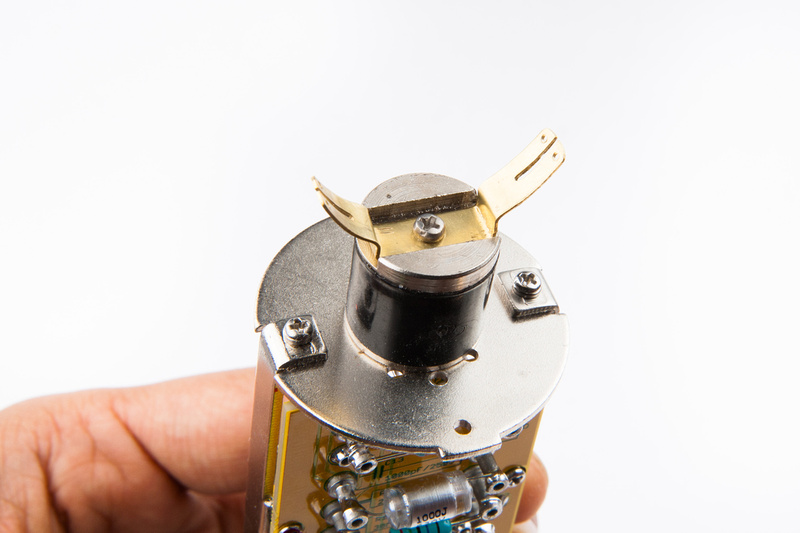
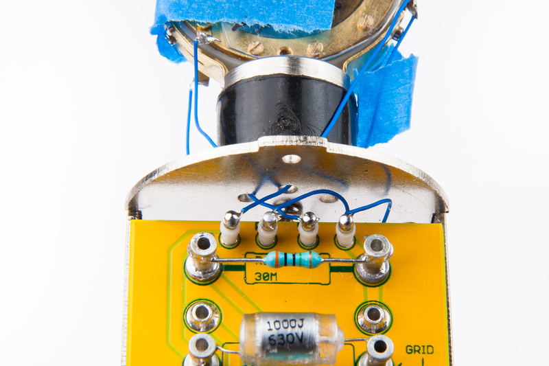
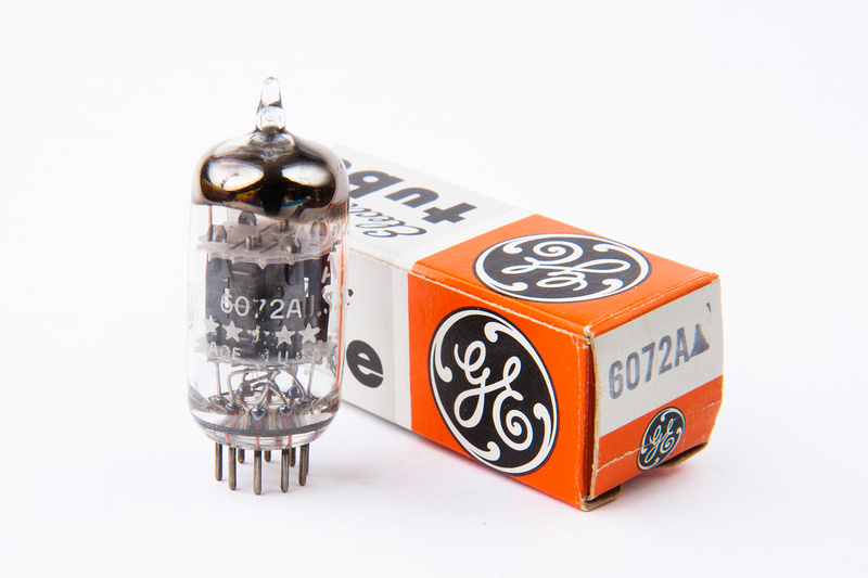
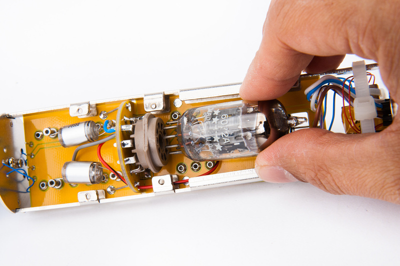
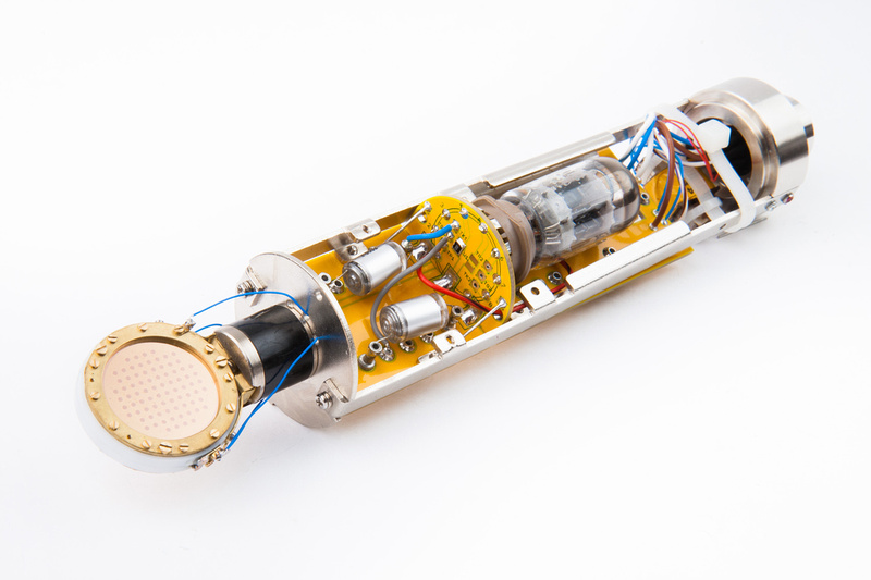
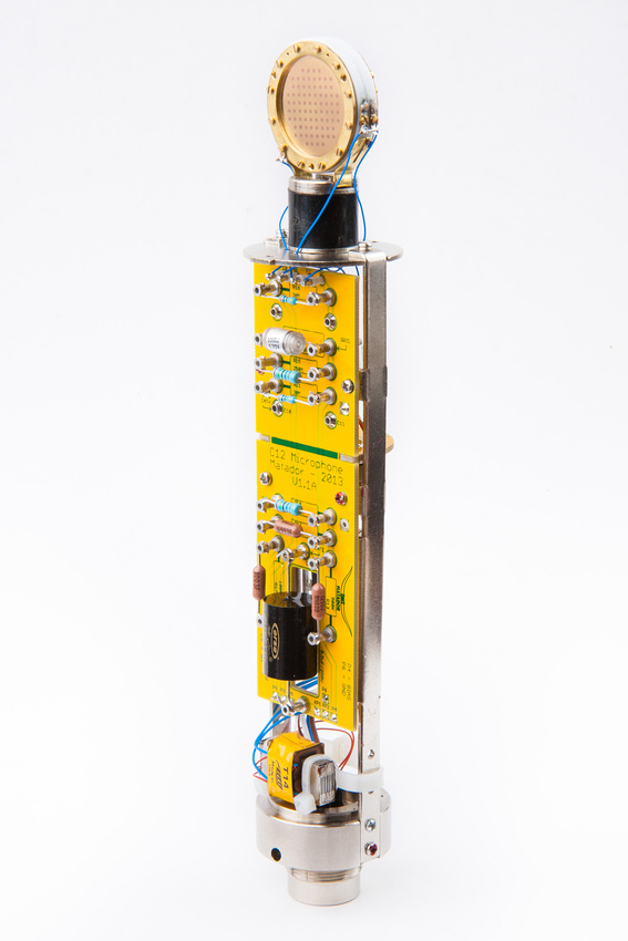
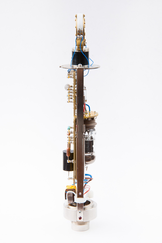
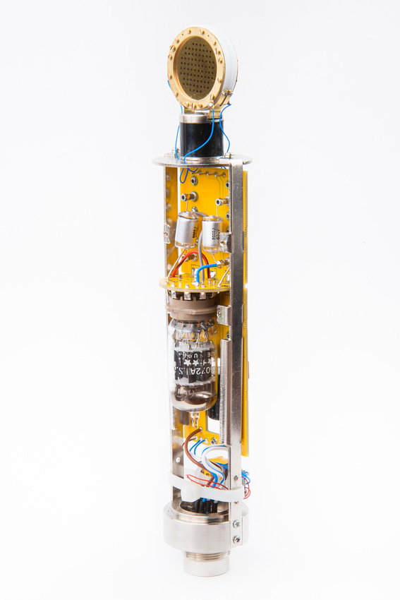
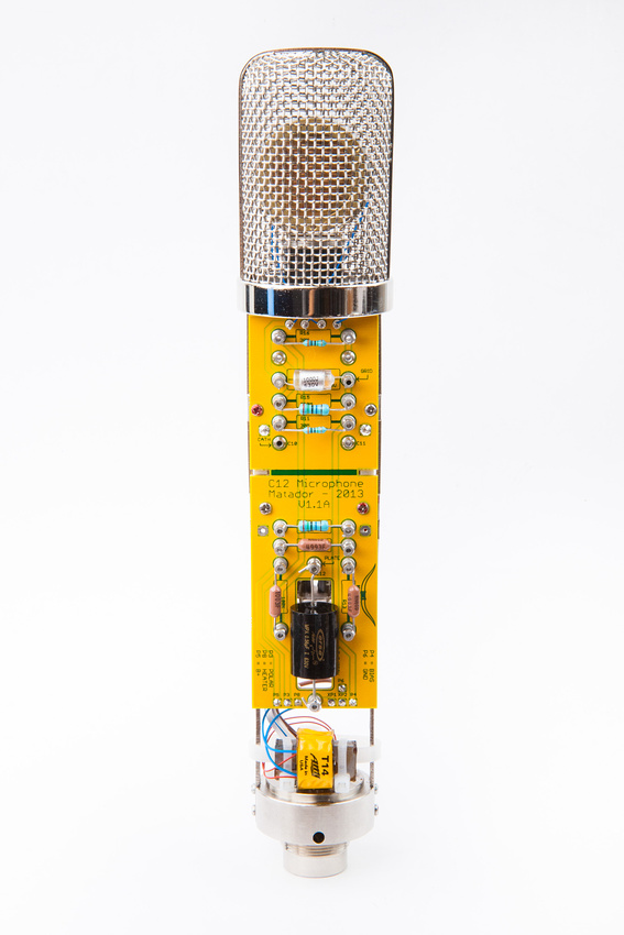
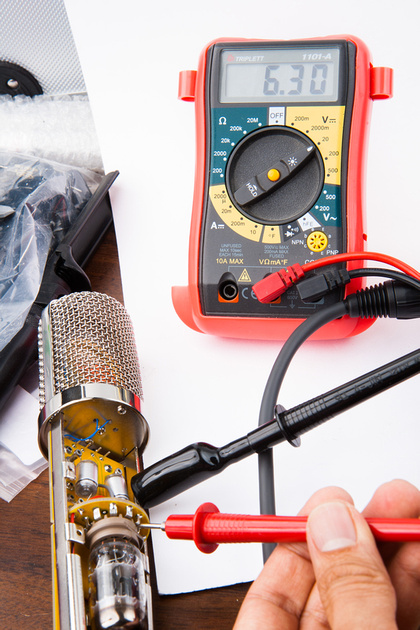
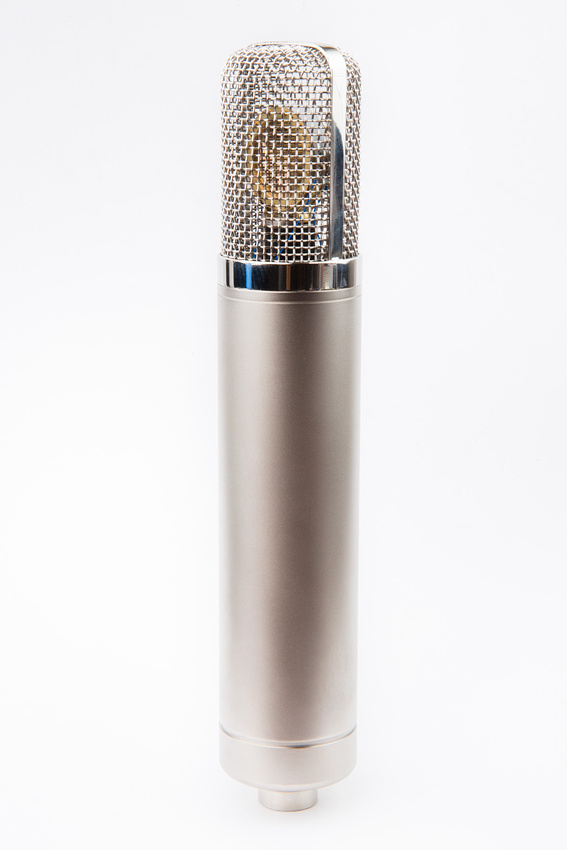
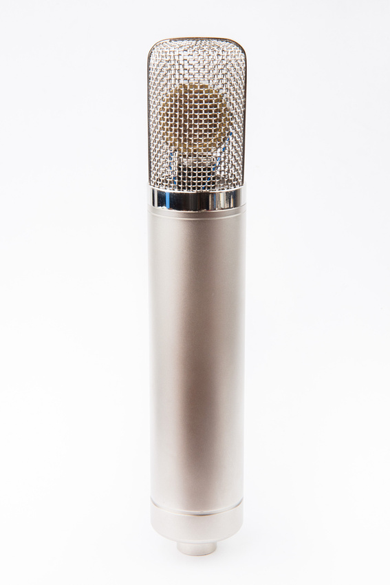
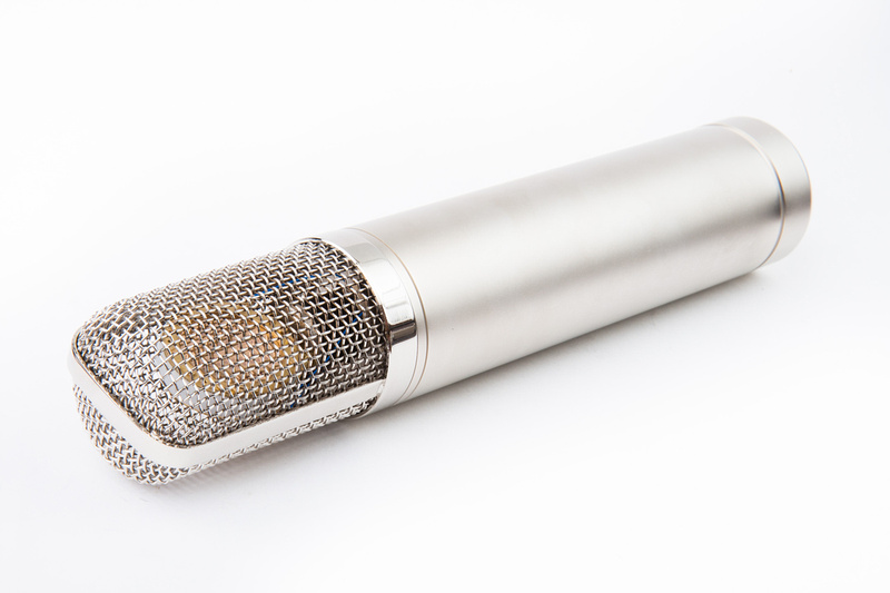
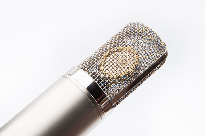
Next, pull the pcb and electronic parts for the microphone preamp. There are really not that many parts in this part of the build, so sorting and locating parts should be pretty straight forward.
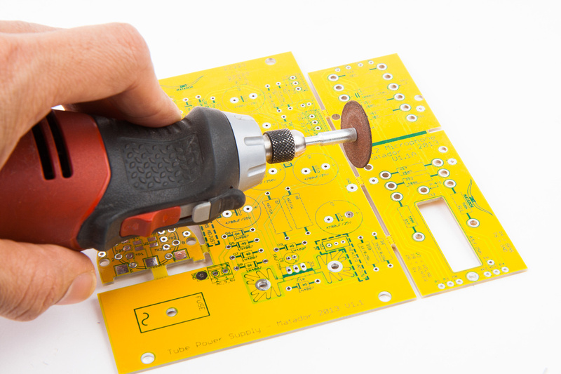
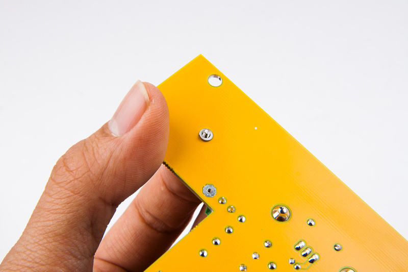
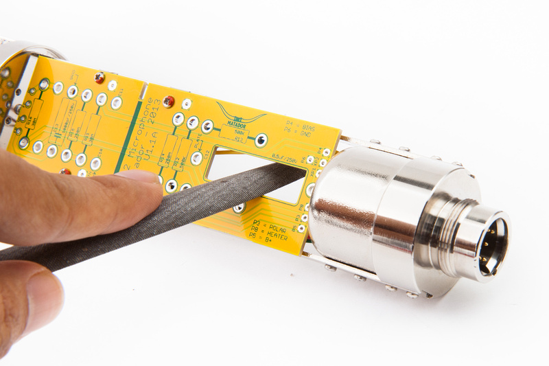
Special Note: For kit builders using the 1uF capacitor option. The kit supplied .56uF original value capacitor does not need any modification to fit. Erse changed the specs on this particular 1uF capacitor that is supplied in kits ordered after 9/6/2013. To accommodate the larger diameter capacitor, file the relief slot in the microphone pcb at a 45 degree angle to allow the capacitor to sit slightly lower towards the center of the microphone.
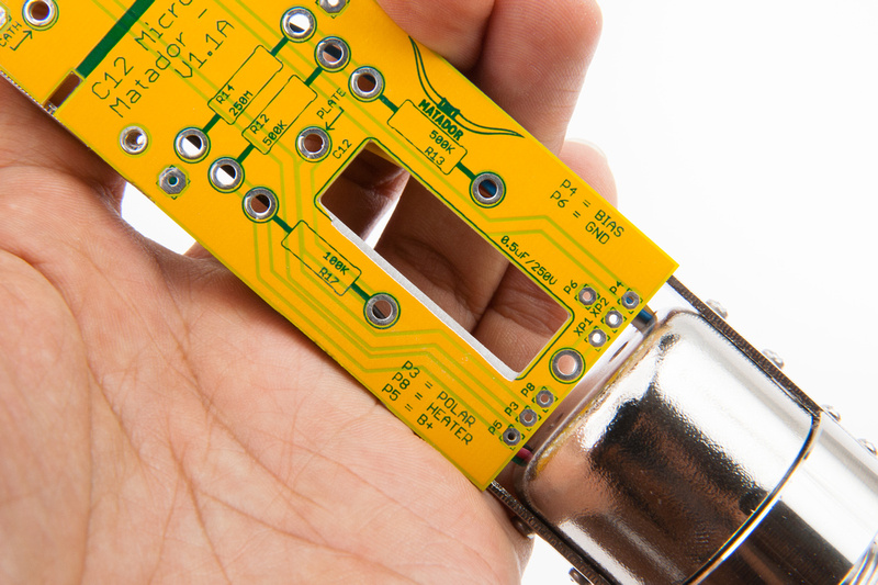
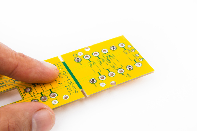
The relief cut looks like this when finished.
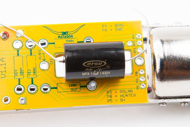
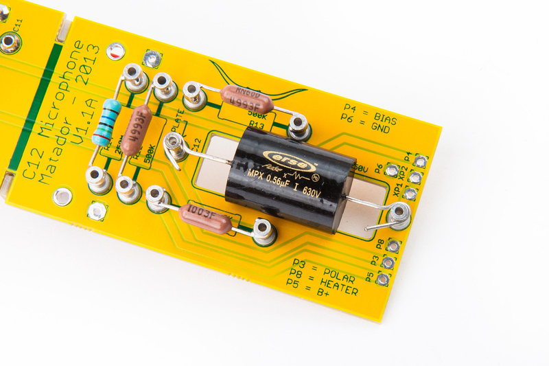
The final fit for the capacitor does not leave much wiggle room, but this maximum dimension capacitor fits. Be careful soldering around the R17 turrets and they are very close to the capacitor.
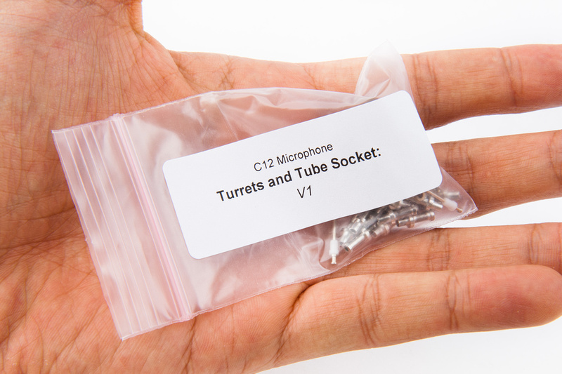
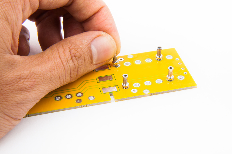
Pull the turrets first to prep the board for mounting the components.
4 turrets are mounted on the back side of the pcb to accomodate capacitors.
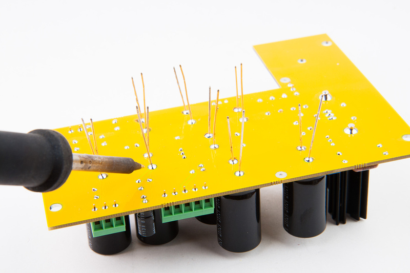
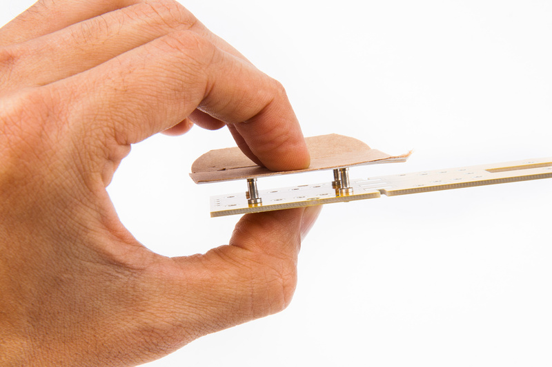
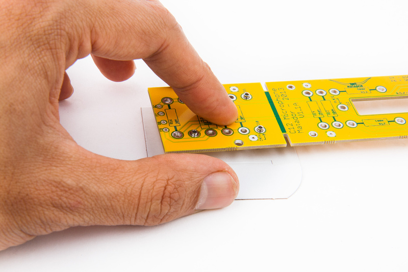
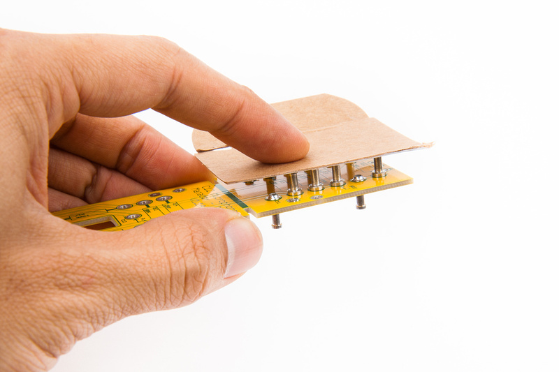
I use a piece of cardboard to hold the turrets in place and flip the whole assembly to solder from the back side.
Press firmly down on the pcb while soldering the turrets to make sure they stand up straight and seat flush to the pcb.
And here are the 4 turrets that mount on the back side of the pcb soldered in.
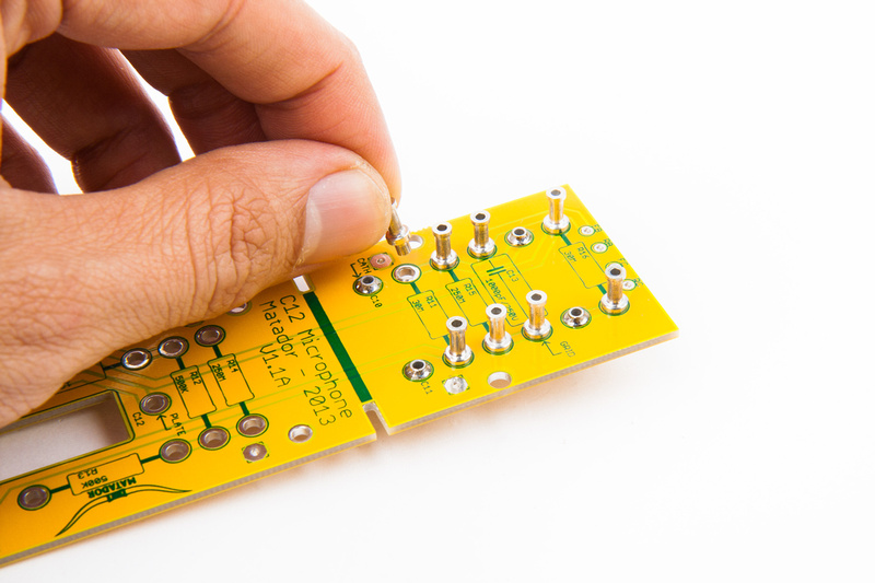
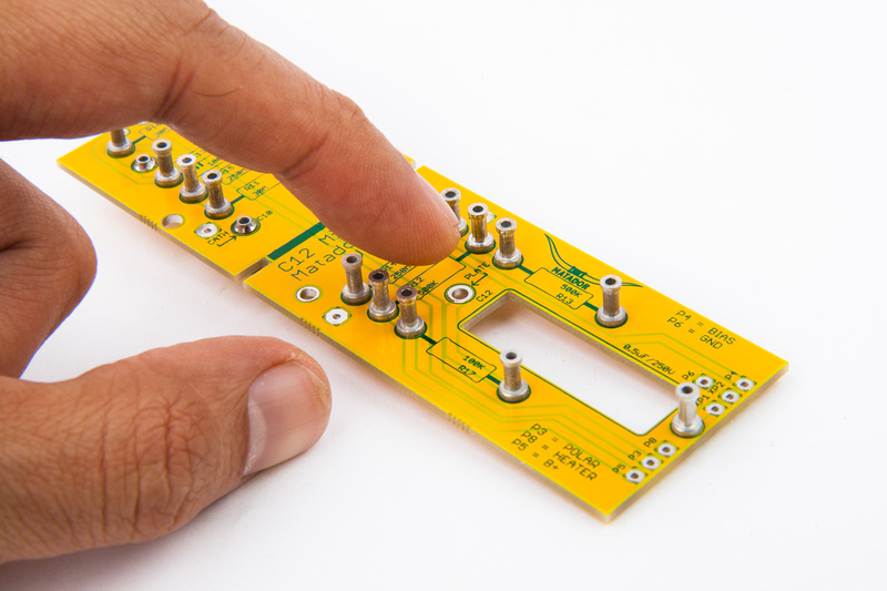
Next, begin installing the front side turrets in the same manner.
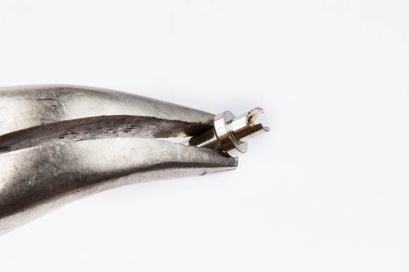
Because the tube mounts to the back side of the pcb, to improve clearance, modify this turret for the C12 capacitor before installing.
Using a cutoff wheel on the dremel, cut a notch into the bottom of the turret.
A wire will fit into this notch and allow the tube to have a little bit more clearance over the top of this turret.
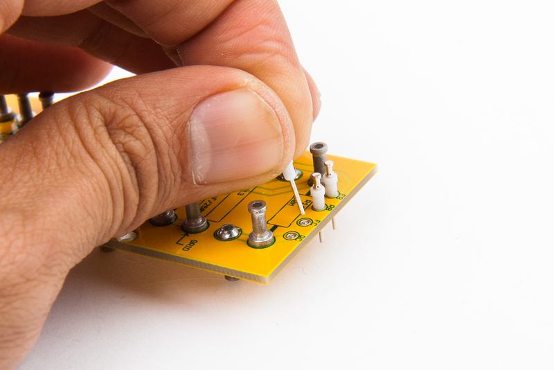
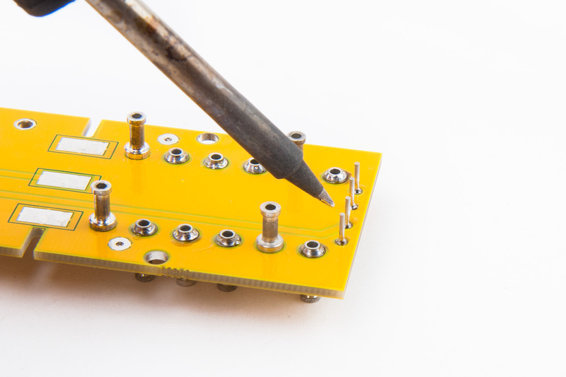
Next, install the 4 capsule connection pins to the pcb. In this build, we solder these in from the back side.
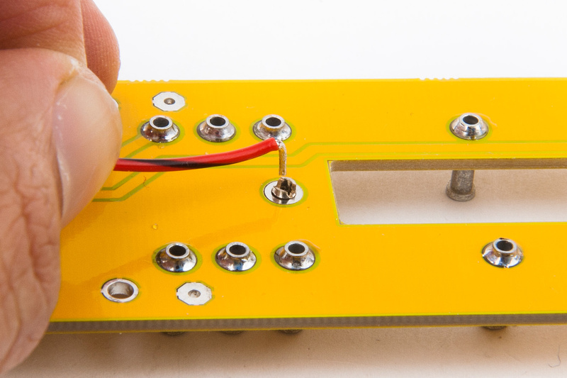
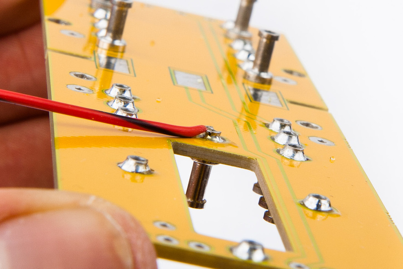
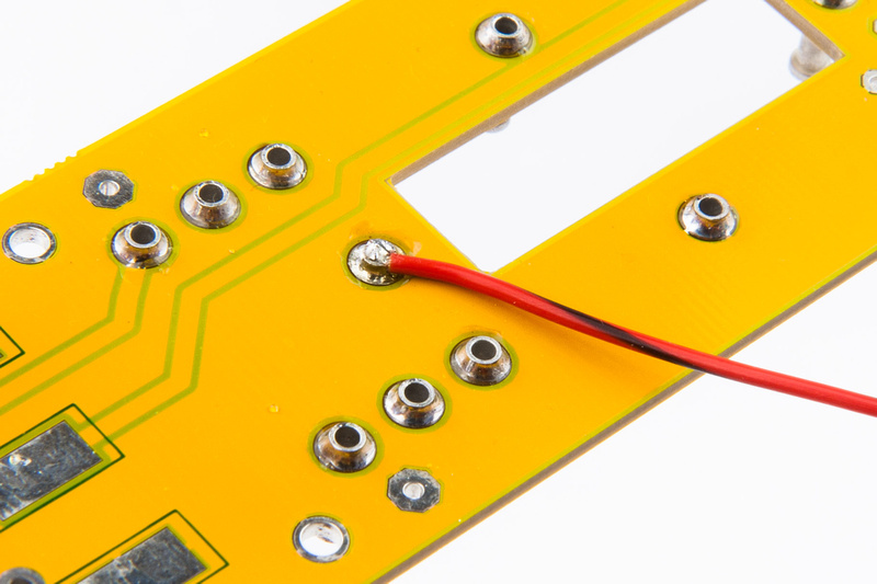
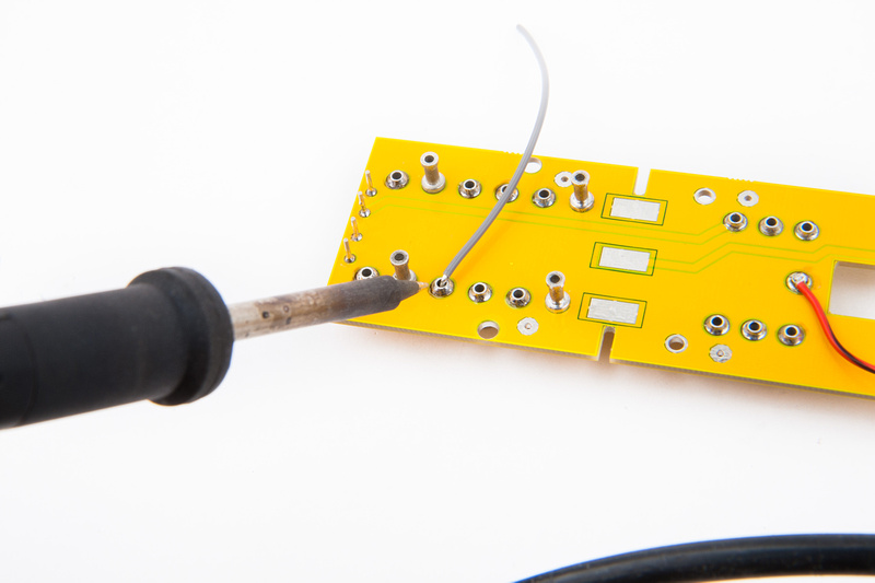
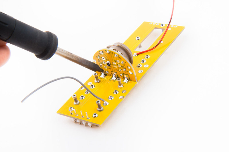
Connect a length of wire to the bottom of the turret labeled "grid". I select a gray wire.
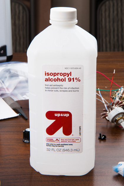
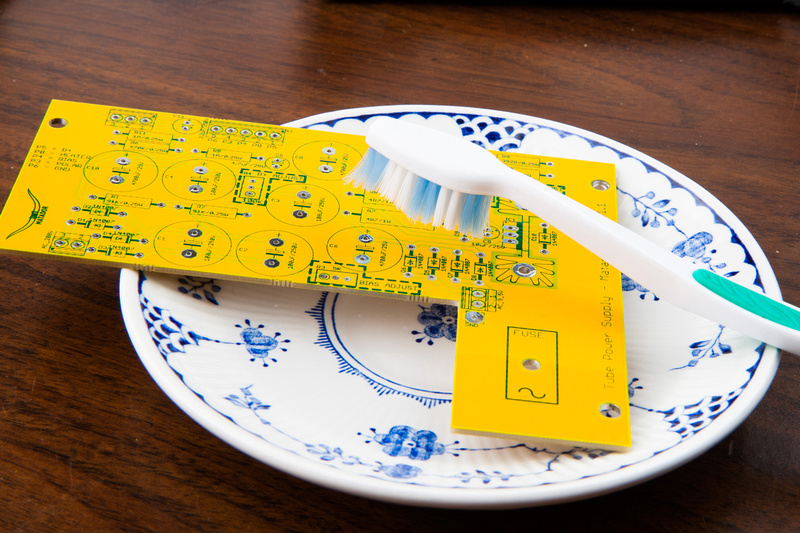
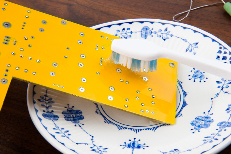
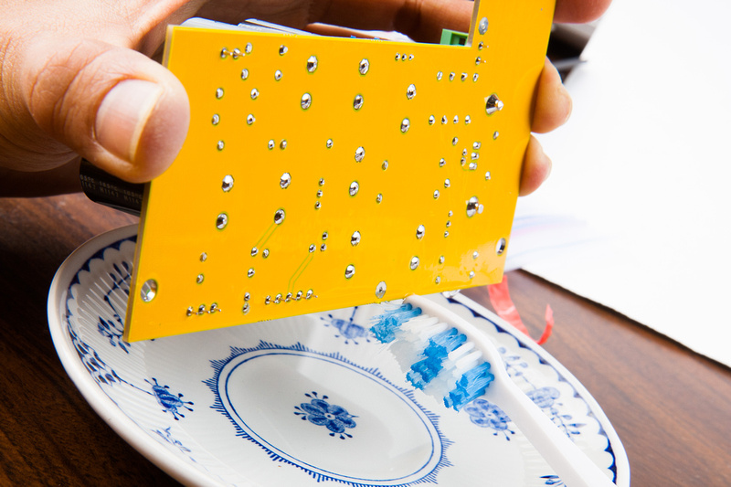
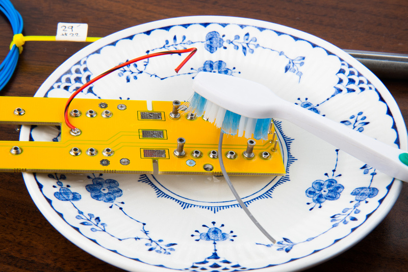
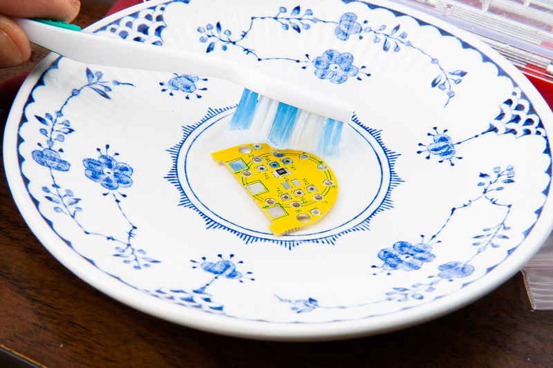
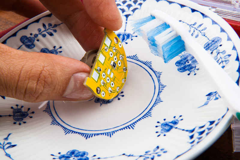
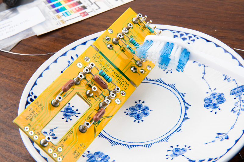
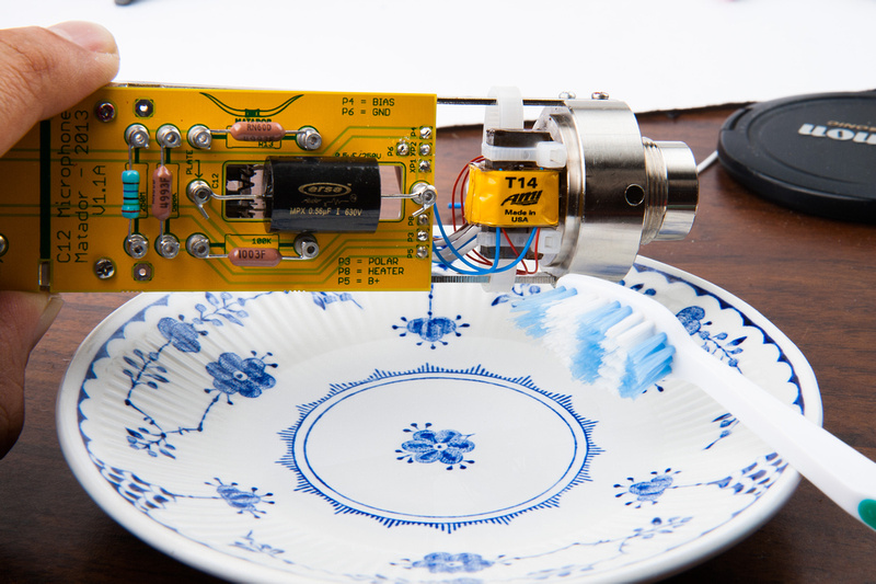
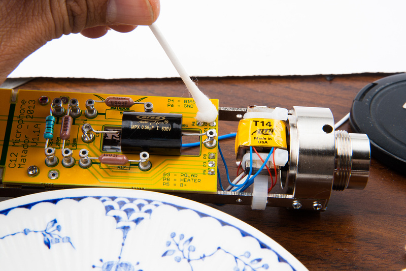
At this stage, it is a perfect time to scrub the board down with some 90% isopropyl alcohol to clean off flux residue. If there is a part that is most important to clean, it is at the base of these turret connections and around the tube pcb that we will install next. This is a non-optional step. Unlike the power supply, the high impedance sections of the microphone pcb need to be kept impeccably clean in order to avoid any leaks that could lead to noise and other problems. Liberally dunk the assembly into the alcohol and use a brush to mechanically loosen and dissolve all of the solder flux.
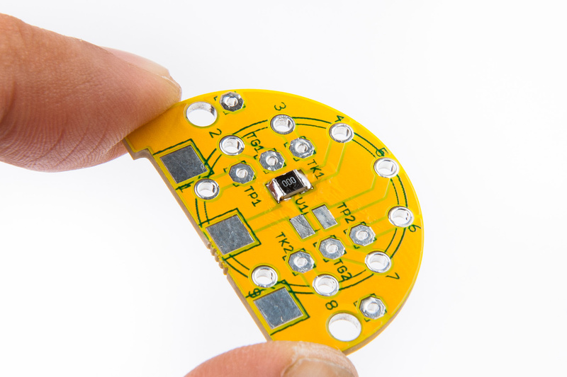
Next, pull the tube-mounting pcb.
Important note: The plate follower topology of this microphone circuit only uses one half of the tube. We can choose to use either the left side "TK1, TG1, TP1" or the right side "TK2, TG2, TP2". If using expensive and increasingly rare NOS tubes and building more than one microphone, I strongly recommend wiring the microphones to utilize opposite sides of the tube. This way, the tubes can be switched between the microphones and the service life of the tubes doubled or at least significantly increased.
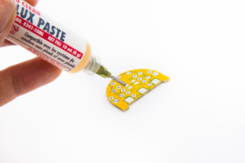
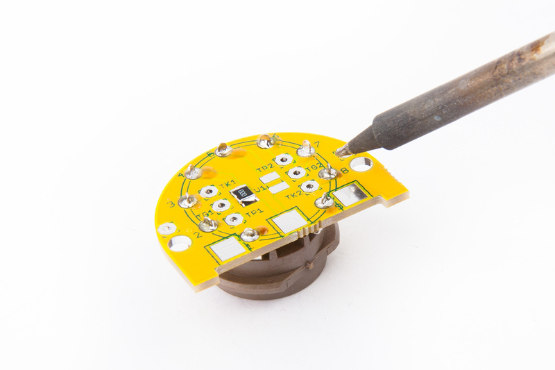
We will need to mount a SMD zero ohm resistor to connect the heater voltage to whichever side of the tube you choose to utilize. I will use the left side "TK1, TG1, TP1" for this build. To mount the SMD zero ohm resistor, first apply some flux to the pads. These come in different forms. I use a paste because that is what i have in my toolbox.
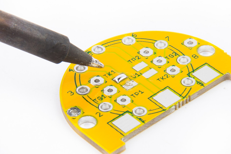
Apply a small amount of solder to one of the pads.
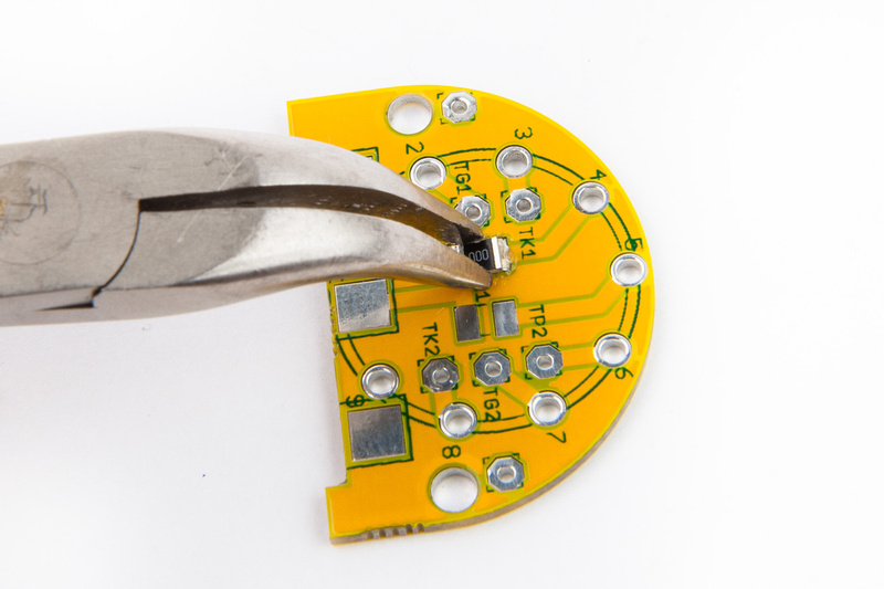
Next, re-apply flux to the pad and use tweezers or in my case some small needle nose pliers to position the resistor while re-melting the solder that was previously pre-applied to the board.
Once satisfied with the position of the component, solder the opposite side as normal.
Don't tell anyone, but that was my very first SMD component. . . not as difficult as some make it out to be.
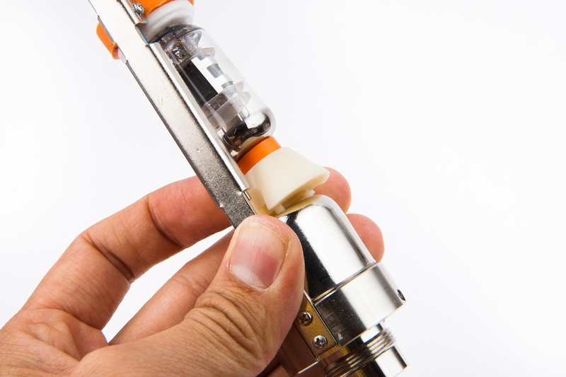
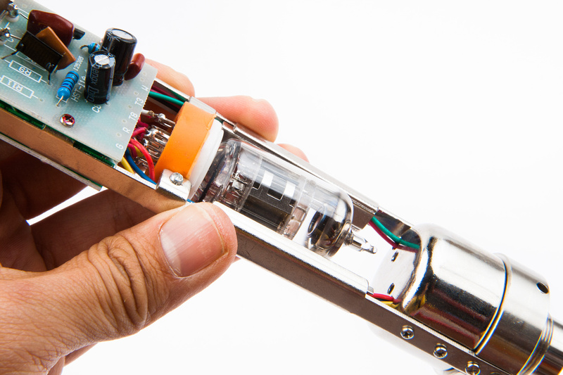
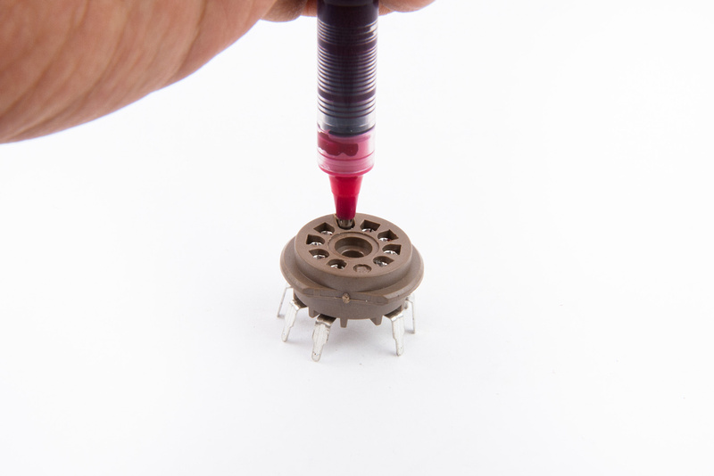
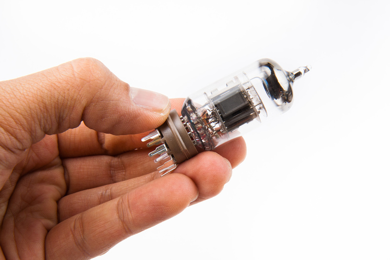
Next, install the tube socket. We will need a tube we do not care about at all to loosen up the sockets because they are very stiff when new. A good candidate is the stock tube inside the HT-11A donor microphone. The bottom portion of the spring-loaded tube shock support easily compresses and kicks out the side of the microphone frame.
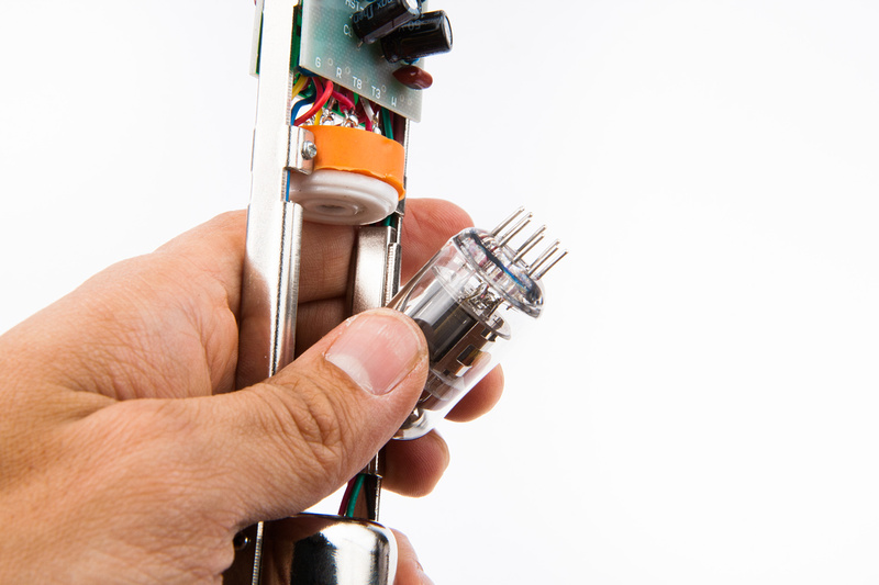
Once the lower support is out of the way, the tube can be easily removed.
I use a pen to gently loosen up the tube sockets because I could not insert the tube into the socket otherwise without risking bending the solder leads. Do not loosen them too much. Just enough to allow insertion and removal of the tube but retain a solid grip and contact.
And test fit the beater tube to the socket.
Next, I dunk and scrub the pcb in alcohol.
If you pen leaked all over the tube socket like mine did, it wouldn't be a bad idea to clean that also in alcohol before fitting to the pcb.
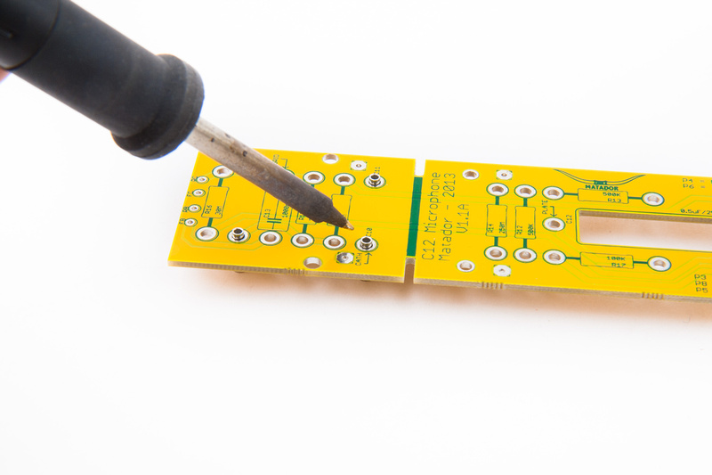
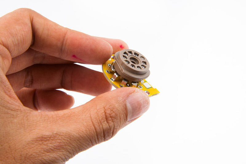
Next, solder the tube socket into position.
And clean the flux off. These connections are very important to keep clean.
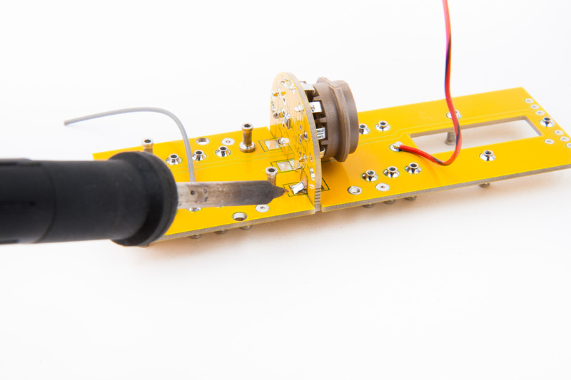
Align the 2 pcb's and solder one tab.
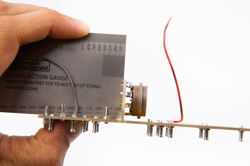
Using a straight edge as a guide, re-heat the pad and align the 2 pcb's to perfectly perpendicular.
Once satisfied with the alignment, solder the remaining accessible tabs.
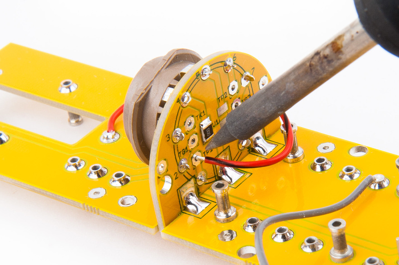
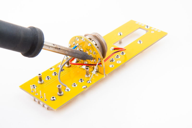
At this point, attach the previously attached red wire to the plate pad on the pcb marked TP1 (or alternately if building the left-side of the tube TP2).
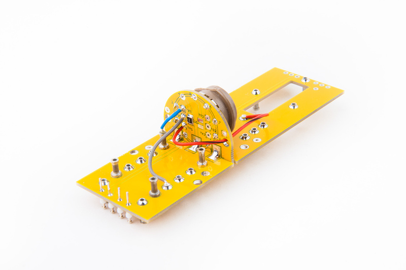
And connect the gray grid wire to the "TG1" pad and install a new wire from the turret indicated for cathode to "TK1"
IMPORTANT NOTE: Version 1.2A PCB's have a screen printing difference from version 1.1A. The screen printing indicating "CATH" (the cathode wire connection point), has moved from the C10 turret to the C11 turret. As this a ground point, either location will work for connecting the blue wire. Following this build thread exactly as pictured works without problems. Changing the ground point to the C11 junction also works 100%
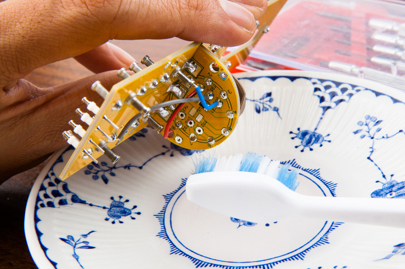
Next, clean the pcb of solder flux.
The pcb has provisions for triangulating support braces for the tube pcb. Wire lead cutoffs from the large psu capacitors can be used to create these supports.
And all turrets are installed at this point and we are ready to populate the pcb with electronic components.
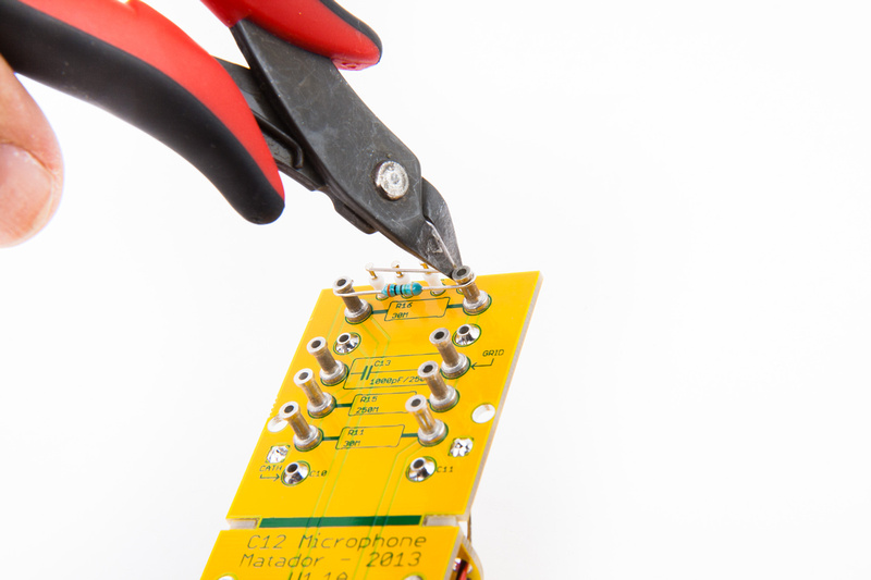
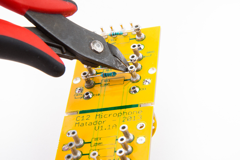
There are many ways to attach components to turrets. I choose to wrap the components around the side of the turret. They can also be inserted directly into the top holes. If wrapping around, mil-spec is to use half of a turn at each connection. Populate the resistors first.
For builders who wish to use the 12AT7 tube in their build instead of the original 6072A tube, a 47K resistor should be substituted in the R17 position.
Part Number RN60D4702FB14
Be careful with the temperature setting on the iron and the length of time heat is applied to the turret. If left on too long, the turrets can come pull away from the pcb and it is a drag re-setting them into the pcb.
And resistors are in place.
While it is not completely necessary to clean these connections, this is the last chance to really dunk and scrub the board because the capacitors do not like exposure to isopropyl alcohol.
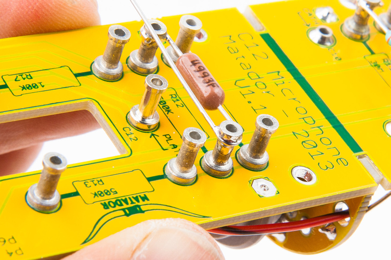
Next, I install the output capacitor. Note the configuration of the wire leads. I wanted to make a 100% solid connection while retaining the ability to swap this capacitor easily if I decide to move up from the original .5uF specification to a 1uF cap. I leave enough lead to pull on with needle nose pliers.
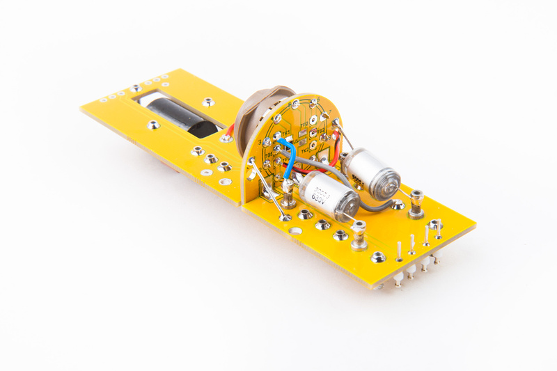
Next, the 5000pf caps are installed on the back side of the pcb.
And the 1000pf capacitor on the front side. The mic preamp board is now fully populated.


