DIY Console power supply, which one to choose?

GroupDIY Audio Forum

Help Support GroupDIY Audio Forum:

This site may earn a commission from merchant affiliate links, including eBay, Amazon, and others.

Olegarich

Well-known member
GDIY Supporter
Joined
Aug 30, 2012
Messages
244
Location
Vilnius_Lithuania
Dear DIY family. I want to build power supply for my trident 924 console. The old one is pretty noissy and that affects all the sound. Besides that, there are a lot mess around inside (not original) and it looks pretty bad so i want to make new one from scratch. the console needs +18 -18 +48 and ground 5 Amps.

I've build some studio gear (1176, gssl) so soldering is not problem for me. What I'm looking for is some advices from you guys.

Do you know any good schematics for this kind of project?
what power supplies are good and bad for this applications?
What should I avoid building power supply for a recording/mixing console?
There are some PSU for consoles but they cost a fortune, can enyone tell me why?
If you have any link to project or mabe made any by yourself I would be very thankful for your help or any advice you can give me.

Thanks,


Hi,

CPS275 from Soundcraft may be a good choice, IMO.

http://www.soundcraft.com/downloads/fetchfile.aspx?cat_id=user_guides&id=3221

Regards,
Milan
 
Hi,

Console power supplies of 5 amps..... be wary, and also be aware......

Low current PSUs of an amp or two really are easy to design: - follow data sheet, build circuit, project complete.

To do it right you need to be willing to spend a lot of time and money to develop a 5amp (or greater) PSU. You will need access to good test gear (meters, dummy loads that mimic a console's load characteristics, sensitive noise measuring equipment, etc,).
My advice from 3 decades of pro-audio design & development work is to buy a ready-made PSU. Someone else has already had the double hit of financial pain of buying & developing test gear and of getting the PSU design & build right. Having both developed and repaired console PSUs up to at least 15 amps, I can honestly say they can be a minefield for the experienced...... and far worse for the unwary!

A few points for consideration are:

Building a power supply that can give 5 amps is easy.

Getting it to perform at 5 amps with an acceptably low noise, say better than -80dBu, is more challenging.

Circuit schematics and semiconductor applications notes only tell part of the story. To achieve a PSU of quality performance you will NEED good test gear.

PCB layout is critical:  fractions of an inch make a difference.

Physical layout is critical:  wiring, connection points, electrical safety, thermal performance, thermal safety.

Safety & reliability:  over-voltage sensing, under-voltage sensing, voltage tracking, over-current sensing, over-temperature sensing, mains power wiring, stored energy in reservoir caps, clearance gaps between mains and low voltage DC wiring, double insulation.

There is a very good reason why high-current PSUs that achive high levels of performance command such high prices.


Hope this helps,

Gareth.

 
Designing a console power supply is not rocket science, but the higher current/power involved means you need to account for proper heat sinking of pass devices, how and where regulation circuitry is referenced, and more details like capacitor values, that are not a matter of concern in low current design.

It is useful to appreciate what the console needs or is looking for from the power supply. I have made consoles with 3 terminal regulators on every strip so the bulk power supply was just a pre-regualtor with smoothing, not a precise final regulator. If this is the only regulation for the console rails it needs to be more rigorous.

Don't ignore voltage drop in wires and impedance of the wires, between PS and console chassis, while I expect all consoles add sufficient capacitance on rails inside the console.

Historically console power supplies are not over designed, and many console designers learned about power handling (similar to designing power amps) by doing their first attempts wrong  (who me?). 

At 5A you can just about use off the shelf 3 terminal regulators, which is not a bad idea if uncertain about your design chops, and they should have app notes to help with heat sink needs etc. .

JR
 
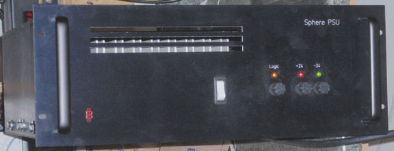
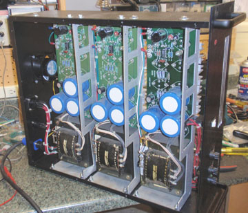
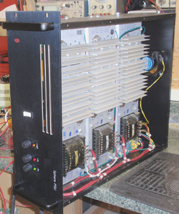
If you look inside a mozart powersupply, there are three to four OEM supplies by Power One.  (Linear type)

These can be purchased in the International Series from digikey or mouser,  up to 9 amp at 15 volts and with a quick mod, go up to 18volt for $120 each.  Two will get you a bipolar supply and add others for logic and phantom.  Just put them complete into a rack with some air cooling and you have a replaceable module based Power supple.  Very cost effective and bullet proof.  Also have sensing inputs if needed.
 
fazer said:
If you look inside a mozart powersupply, there are three to four OEM supplies by Power One.  (Linear type)

These can be purchased in the International Series from digikey or mouser,  up to 9 amp at 15 volts and with a quick mod, go up to 18volt for $120 each.  Two will get you a bipolar supply and add others for logic and phantom.  Just put them complete into a rack with some air cooling and you have a replaceable module based Power supple.  Very cost effective and bullet proof.  Also have sensing inputs if needed.

Good example..

SPHERE_PSU_FRONT172.jpg


SPHERE_PSU372.jpg


SPHERE_PSU272.jpg


3    13A  24V power one  supplies

Got them cheap on ebone

Best

GARY
 
I have two International Power 15V & 6A linear PSUs. The output voltage is adjustable and will go up to 18V. These will do the main rails. I also have again an International Power +48V @ 500mA for the phantom. Please PM if it is of interest.

The one on the below link I posted in the BM is the 12V version but the 15V versions are identical.
http://www.groupdiy.com:80/black-market/f-s-international-power-psu-12vdc-6-8a/
 
Hey guys, can you point me , wheer I did mistake

I've build +18 and -18V power supply with 2 separeta supples which give +18 each.

SO i've pluged them this way:

From first supply + goes to negative - it's coneccted to mains Ground and to console ground

from first - goest to -18 from second plus to +18v.

But it' pretty weird, that when there is no load, both works well, but when I plagin in console, then after i turn on supply 18 works and there is no -18, i turned off and turned on again, now it's -18 Works and there is no 18V, i turning off and on, and once it +18 then it's -18V, probably i have connected something wrong, but what???

 
Hi Brian,

I supplied the PSUs. They are International Power single rail 6A modules. They came from a Lexicon Opus console.

Oleg e-mailed me tonight but I was leaving the office to collect my son.

However, although I explained to him how to wire them his description above does not really reflect what I said.

Oleg,

Please see attached wiring.

- of power supply no1 connects to the + of the No2. This is your Common Ground.

+ of power supply no1 is your positive rail.

- of power supply no2 is your negative rail.


Could you please verify that is how you wired it?
 

Attachments

  • Oleg_psu.jpg
    Oleg_psu.jpg
    10.6 KB
Presuming the wiring is per Sahib's diagram, a possibility is that the supplies are having a tough time dealing with the Trident's inrush current(s).

I have bumped into this problem more than a few times with desks I refer to as "hard to start".  There are a variety of solutions I've encountered, or figured out myself.

That is a topic within itself, which may be worth discussing on this forum.

Bri
 
Sahib, yeah that the right scheme that you draw, I did like this.

First I thought that it's not enough power (amp) friend of mine told me that it have to be 10 amp and if I'm using 2 PSU by 6A it's not giving me 12 in total. But then I realized that every rail before going to console have "out" fuse (from old supply) and there is 5A fuse inside, so If I'm right I have to feed every rail with 5A. So in my case First PSU feeds positive rail with 5-6A and second feed negative rail with 5-6A so everything is Ok here, right??? Am I right?

Today I noticed one strange thing, i turned on PSU and both rails worked well. After I turned it off and then turned it on and it started to act like i described before (Only one rail working). Then I turned off console 16 channels ( moved out power cables from channels inside console), to try is it about power. Turned on PSU, Wola- everything works well, 18 and -18 volts, after turning vol adj trim PSu now gives me nice 18 and -18V with console plugged in, but without 16 channels, (24 left).

So I wonder:

1. If 5A to each rail is to small for 40 channels??? If it is, then why the old one used 5A fuse????
2. Why there was one time when I turned on PSu and it worked and after restarting it it started to act like before???

Thanks for suggestions and help, really thanks a lot. Hope you have some ideas what it might be
 
As I mentioned, I've seen problems like this before, and it always appear to be due to inrush current.  In a large analog desk, a bazillion electrolytic capacitors across the PSU rails have to quickly charge when power is first applied, and thus a large current spike can cause the PSU regulators to go into current limiting.

On the International Power modules, there should be a trimmer pot marked "I LIM" (or something similar) which sets the current limiting threshold.  Make note of the existing position of the trimmer and try adjusting it.  Which direction?  In most cases, clockwise moves the threshold UP....but not always, depending on how the manufacturer designed the circuit.

Amek used the International Power IF-15-15 modules (single rail, nominal 15 VDC but modded to adjust up to 17.5 VDC, 15 Amps) in multiple times for their giant 9098 desks.  In addition to the resistor change for voltage trim, a 2200 uF cap was added between the two overcurrent sense pins on the uA723 regulator chip to "slow down" the response time of the chip to overcurrent.

I've also always wondered why the PSU manufacturers didn't design in a "slow start" to ramp up the voltage after mains power is applied.  I saw that design feature in the "factory stock" PSUs that Trident supplied with the Series 80B desks "back in the day".

I can ramble on on this subject, but will leave with an attachment of the Amek mods.  Sorry about the poor quality, but I did my best to scan a copy of a copy of a copy of.....

The rectangle is a 723 regulator chip.  The added cap was drawn on the original paper copy, while the notes about parts values were added by me.

Bri


Attachments

  • amek pg 2.pdf
    56.2 KB
Hi Oleg,

As Brian said the only explanation is the inrush/start up current.  One psu will always be quicker then the other to shut down. There is indeed a Black trimpot labelled as " I Limit" . As Brian said mark the current setting with a permanent pen on the edge of the trimpot for your records, and try to set it to handle the start up.
 
With power amps, I've had trouble with in-rush from reservoir caps blowing the rectifiers into a million pieces. I ended up using a fairly crude, but effective soft-start circuit, where a current-limiting R is always in series with the mains - and a relay connects the un-limited mains across after a second, the time determined by a cap which has to charge before the coil is thrown.

Not sure if this is useful here - just thought I'd mention it for interest's sake. You could adapt a similar circuit to work in this scenario quite easily. If there's no logic in the console and it's just a bunch of opamps there's no reason why it wouldn't work.

Alternatively, you could adjust the limiting pot, as suggested  ;)
 

Latest posts

Back
Top