Matador
Well-known member
I had an idea a while back based on all of the reports of people complaining about decreased gain on original U87 clones as compared to other large-diaphragm condenser designs (especially the U87AI).
One of the reasons for this is is the difference in polarization voltages between the two designs: the U87 uses phantom power (albeit heavily filtered), and the U87AI uses a switch-mode power supply (SMPS) design to boost the 48V phantom voltage up to +60V. This accounts for about 6dB of sensitivity difference between the two designs. There are many other varients of this design in many Schoeps microphone designs as well.
I set out to design a small SMPS adder board that could be tacked on to existing phantom-powered mike designs to provide a full +60V polarization supply. The intention is for this to be usable in U87 clone designs to convert them to near "U87AI" specifications, but there's nothing preventing them from being used in other designs that lack a full +60V supply as well.
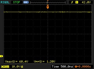
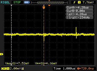
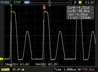
Here is the schematic.. The design is based around an LM5002 SMPS chip with an integrated boost transistor. This chip is good to over an amp, however given polarization supply really have no DC current requirements, the specs of the external parts can be greatly simplified. This design features an input RC filter and an output LC filter to keep it both quiet as well as prevent disturbances of the circuit providing the power to the board.
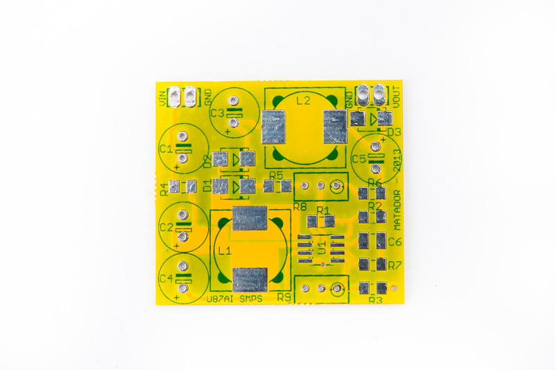
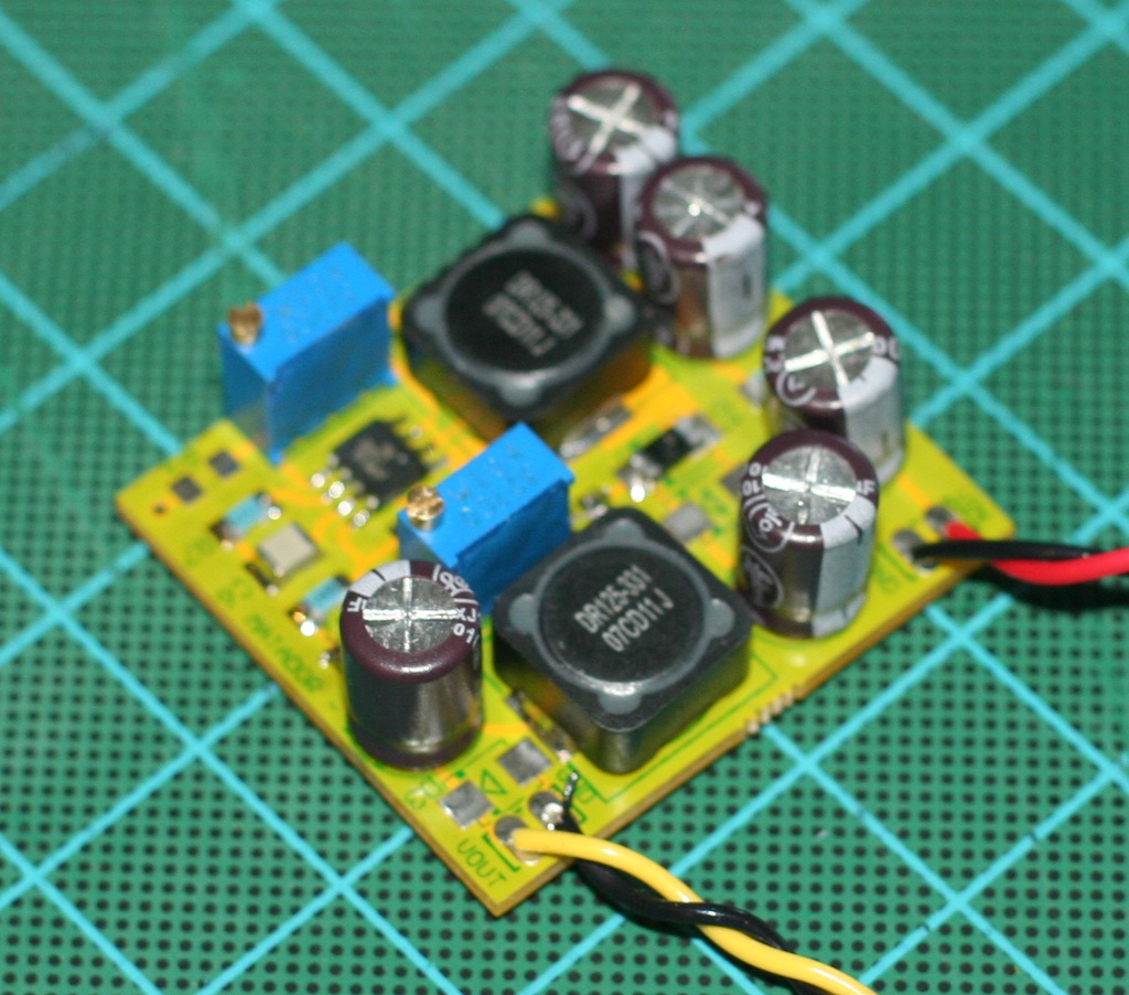
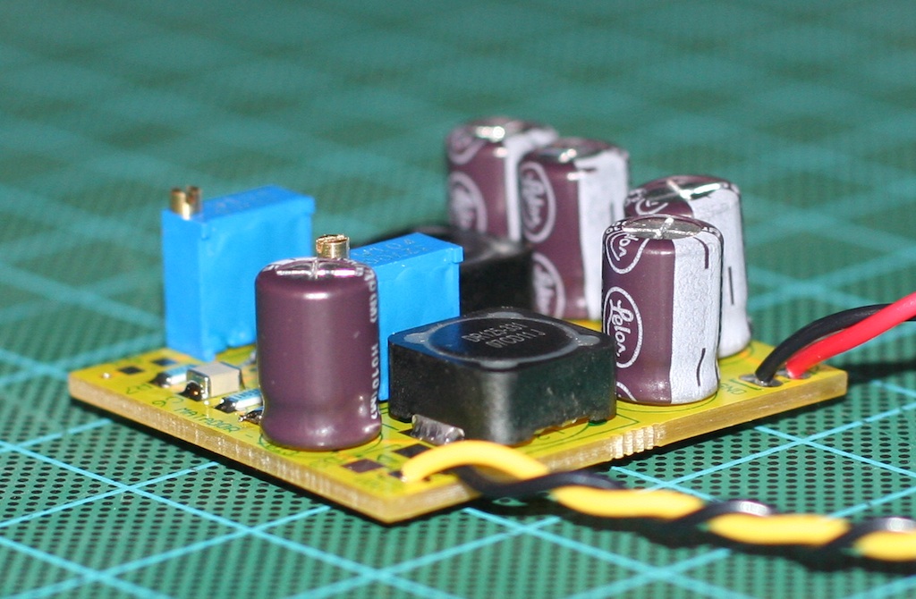
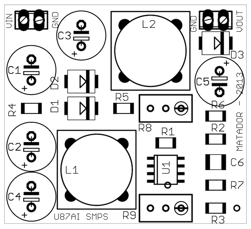
Here is the layout: my goal was to keep it to the same size as a regular 1.1" square DOA footprint, but it ended up being 1.4" square in the end. I used all SMD components except for the low ESR caps, and I may switch the next iteration over to all SMD.
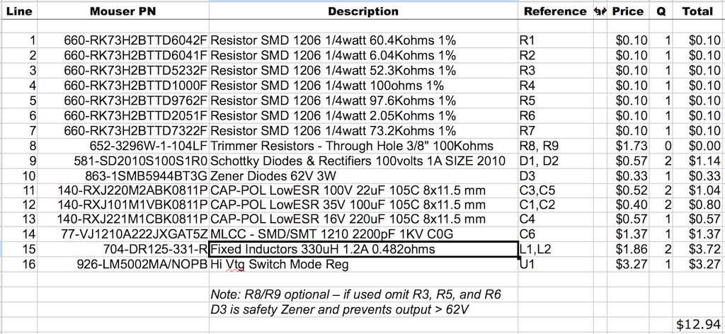
This thread will hold build pics and BOM's to support this project.
One of the reasons for this is is the difference in polarization voltages between the two designs: the U87 uses phantom power (albeit heavily filtered), and the U87AI uses a switch-mode power supply (SMPS) design to boost the 48V phantom voltage up to +60V. This accounts for about 6dB of sensitivity difference between the two designs. There are many other varients of this design in many Schoeps microphone designs as well.
I set out to design a small SMPS adder board that could be tacked on to existing phantom-powered mike designs to provide a full +60V polarization supply. The intention is for this to be usable in U87 clone designs to convert them to near "U87AI" specifications, but there's nothing preventing them from being used in other designs that lack a full +60V supply as well.
Here is the schematic.. The design is based around an LM5002 SMPS chip with an integrated boost transistor. This chip is good to over an amp, however given polarization supply really have no DC current requirements, the specs of the external parts can be greatly simplified. This design features an input RC filter and an output LC filter to keep it both quiet as well as prevent disturbances of the circuit providing the power to the board.
Here is the layout: my goal was to keep it to the same size as a regular 1.1" square DOA footprint, but it ended up being 1.4" square in the end. I used all SMD components except for the low ESR caps, and I may switch the next iteration over to all SMD.
This thread will hold build pics and BOM's to support this project.
")