Hi All,
I have been playing with the Urei 1176 preamp and gain control circuits in LTSpice and I have found that with a few minor tweaks I can make a noise reduction circuit like the DBX or Dolby noise reduction systems or LM1894 chip.
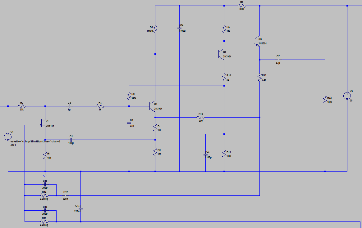
The following is the standard 1176 preamp but I added a smallish capacitor to make the low pass filter (and inductor to make filter 2nd order and lower noise further):
[click on these to make them larger]
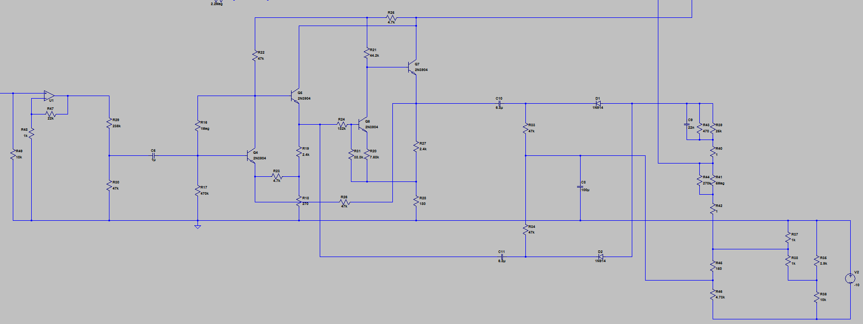
The gain control circuit has been changed so that the bias is 0 (meaning the JFET is biased on instead of nearly off) and the diodes are reversed so that the rectified control voltage goes down and not up (meaning the JFET turns off instead of on in reaction to the presence of high frequencies).
And of course the sidechain has to come from the input (connection not shown) and get boosted instead of coming from the preamp out. And of course the sidechain is high passed in a complementary way to the preamp low pass filter so that only high frequencies turn "off" the low pass filter.
This plot of a white noise burst shows that it's working:
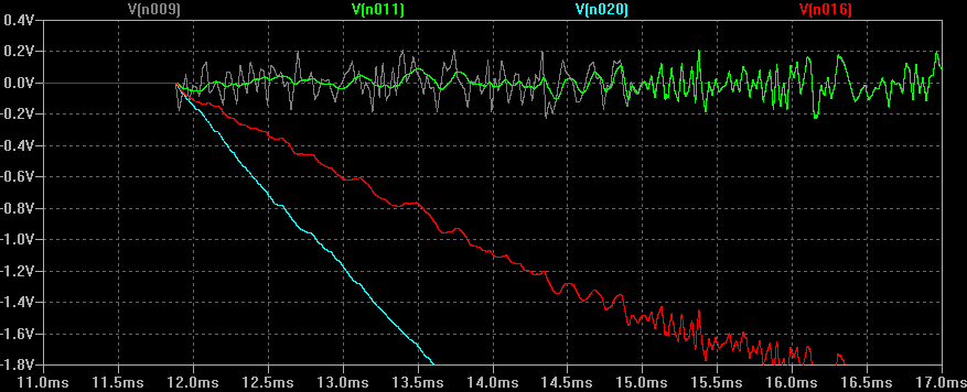
Gray: The input signal (input to R2)
Green: The output signal (actually net of inductor and capacitor connected to JFET)
Red: The JFET gate
Blue: Unmixed control voltage (output of gain control circuit)
So you can see that the high frequencies are filtered until the gain control circuit detects high frequency signal and then it drives the fet off so that high frequencies are passed.
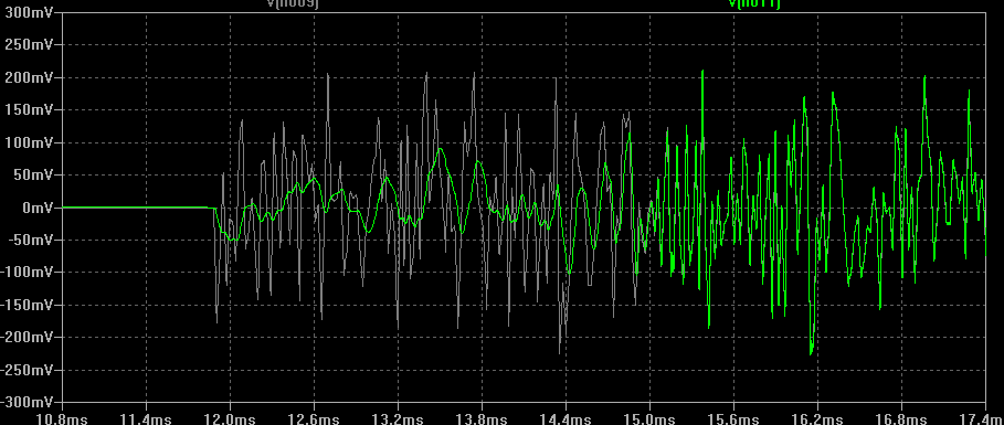
This pic shows a closeup of the noise reduction in action:
This pic shows the AC response of the preamp LC filter and of the gain control LC filter which are of course inverses of each other.
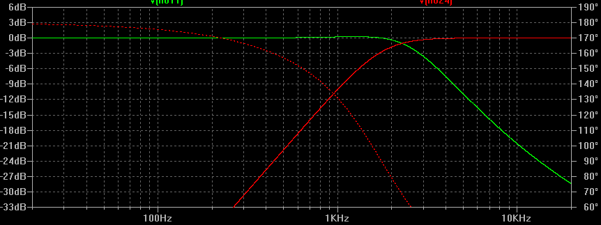
Green: The low passed input when no high frequency signal is present (meaning JFET is on)
Red: The high passed sidechain input means only high frequencies will trigger JFET
The question is, for anyone with knowledge of the aforementioned noise reduction systems, do you think this will work?
I'm thinking about making some PCBs for the 1176 preamp and GR circuits (IO and power handled elsewhere) but I'm wondering if I should add the few components necessary to have an option for this "noise reduction" twist on the 1176 Yeah, it's a little kooky but it might be useful for something like a spring reverb or stand-alone noise reduction unit like the Rocktron HUSH.
I have been playing with the Urei 1176 preamp and gain control circuits in LTSpice and I have found that with a few minor tweaks I can make a noise reduction circuit like the DBX or Dolby noise reduction systems or LM1894 chip.
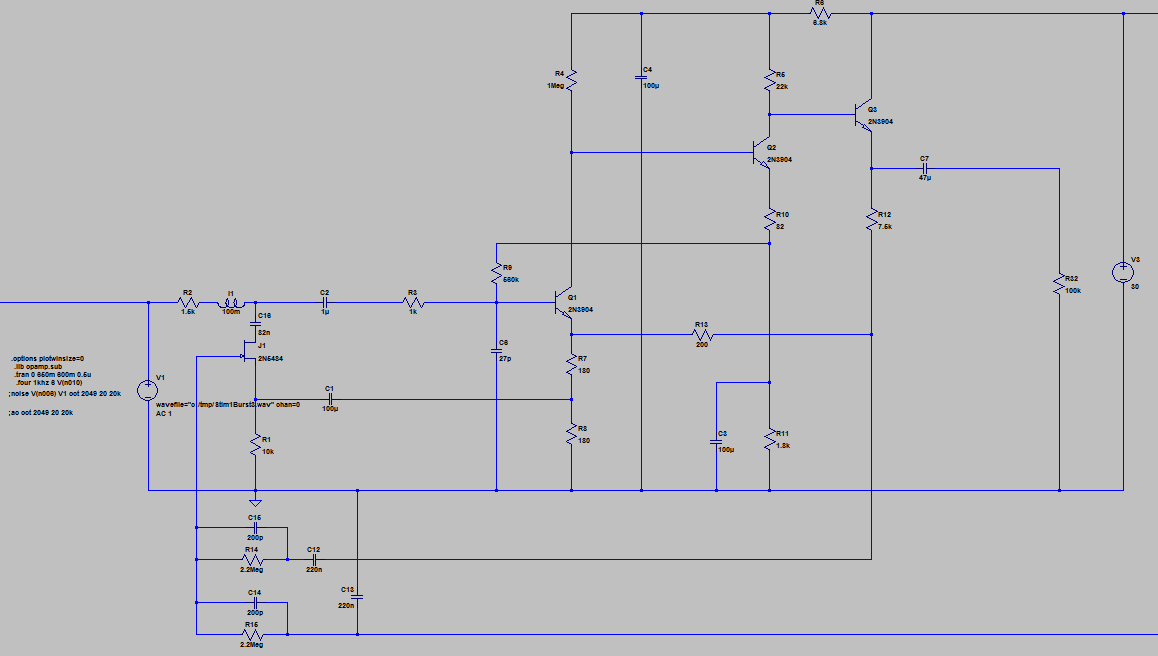
The following is the standard 1176 preamp but I added a smallish capacitor to make the low pass filter (and inductor to make filter 2nd order and lower noise further):
[click on these to make them larger]
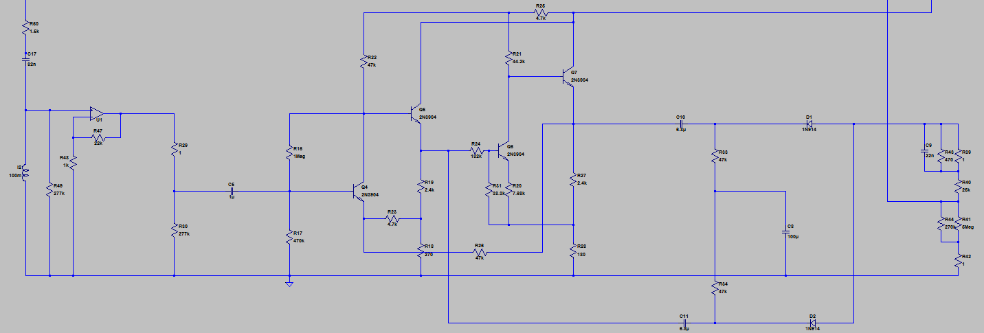
The gain control circuit has been changed so that the bias is 0 (meaning the JFET is biased on instead of nearly off) and the diodes are reversed so that the rectified control voltage goes down and not up (meaning the JFET turns off instead of on in reaction to the presence of high frequencies).
And of course the sidechain has to come from the input (connection not shown) and get boosted instead of coming from the preamp out. And of course the sidechain is high passed in a complementary way to the preamp low pass filter so that only high frequencies turn "off" the low pass filter.
This plot of a white noise burst shows that it's working:
Gray: The input signal (input to R2)
Green: The output signal (actually net of inductor and capacitor connected to JFET)
Red: The JFET gate
Blue: Unmixed control voltage (output of gain control circuit)
So you can see that the high frequencies are filtered until the gain control circuit detects high frequency signal and then it drives the fet off so that high frequencies are passed.
This pic shows a closeup of the noise reduction in action:
This pic shows the AC response of the preamp LC filter and of the gain control LC filter which are of course inverses of each other.
Green: The low passed input when no high frequency signal is present (meaning JFET is on)
Red: The high passed sidechain input means only high frequencies will trigger JFET
The question is, for anyone with knowledge of the aforementioned noise reduction systems, do you think this will work?
I'm thinking about making some PCBs for the 1176 preamp and GR circuits (IO and power handled elsewhere) but I'm wondering if I should add the few components necessary to have an option for this "noise reduction" twist on the 1176 Yeah, it's a little kooky but it might be useful for something like a spring reverb or stand-alone noise reduction unit like the Rocktron HUSH.