You are using an out of date browser. It may not display this or other websites correctly.
You should upgrade or use an alternative browser.
You should upgrade or use an alternative browser.
Vari-mu caps, ripple and oscillation.
- Thread starter DaveP
- Start date
Help Support GroupDIY Audio Forum:
This site may earn a commission from merchant affiliate
links, including eBay, Amazon, and others.
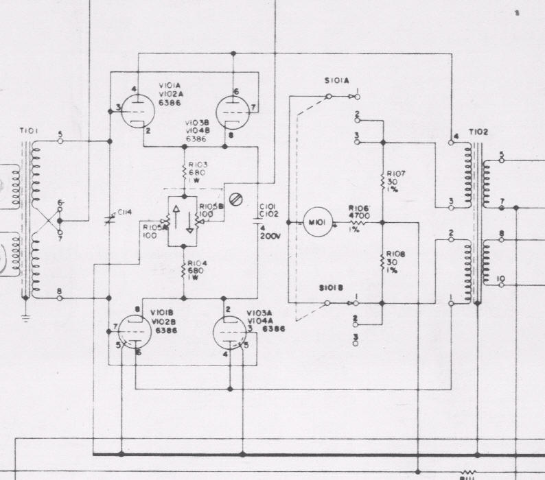
that's the same thing except one is a single stage, the other a push-pull.
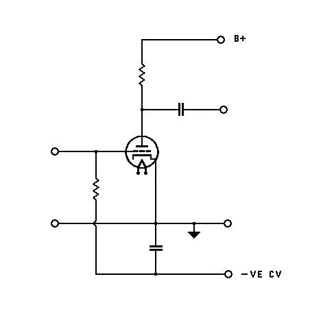
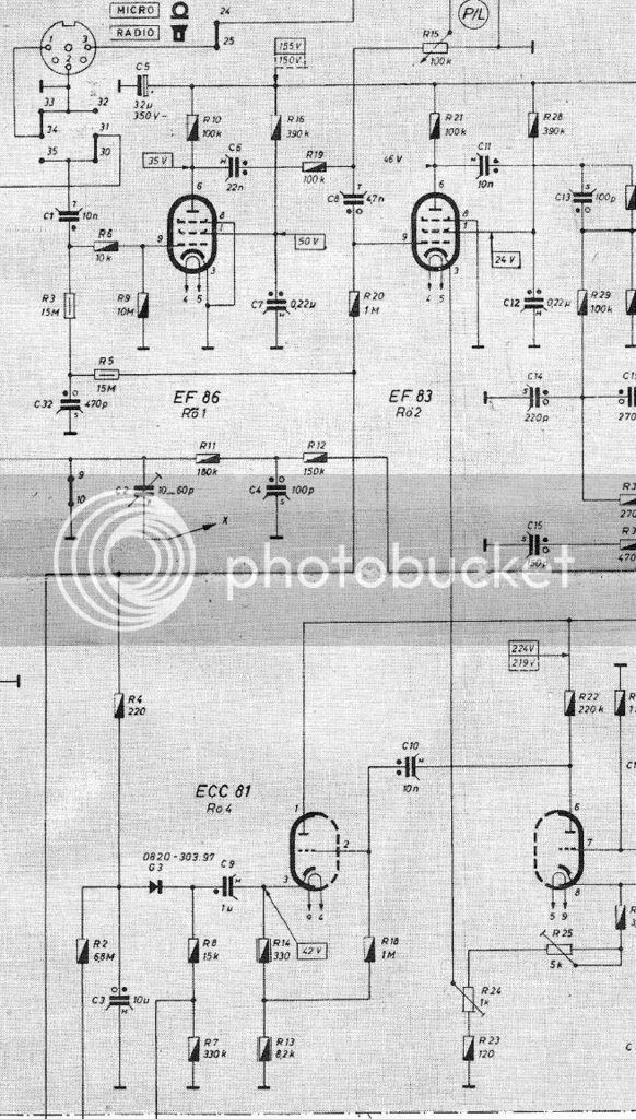
Yes I know, but I drew it like that because I was referring to my post to PRR about radio /tape-recorder circuits.
He described the Grundig TK19 some while back.
Best
DaveP
I don't remember this. Those German engineers were fascinating.DaveP said:that's the same thing except one is a single stage, the other a push-pull.
Yes I know, but I drew it like that because I was referring to my post to PRR about radio /tape-recorder circuits.
He described the Grundig TK19 some while back.
Best
DaveP
Oh dear, we all seem to be at cross purposes here.
That is a Fairchild with which I am very familiar having made that part with 6BA6's.
But what I was interested in was the:-
Quote
You can vary the current by grounding the cathodes and dropping the grid voltage negative. This is a very high impedance, so can be direct-coupled to the timing capacitor (avoiding DC buffers, which were awkward in tube days).
PRR,
The grounded cathode scheme was used in old radio circuits, and the original German tape-recorder circuits, which I believe you are familiar with. Are there any special precautions to bear in mind? If the cap is direct coupled to the grid, do the release caps serve as the grid leaks? Only the Federal and the Altec 436 have cathodes grounded all the rest have cathode resistors.
DaveP
merlin
Well-known member
- Joined
- Aug 17, 2011
- Messages
- 380
The combined resistance of the actual grid leak resistors, and the release resistor in the side chain, form the total grid leak path.DaveP said:If the cap is direct coupled to the grid, do the release caps serve as the grid leaks?
If the cathodes are directly grounded then you'd need to add a bit of permanent DC bias to the side chain, of course. Or you can add cathode resistors instead (LEDs may be better these days). Whatever suits you.Only the Federal and the Altec 436 have cathodes grounded all the rest have cathode resistors.
I think there was just a little detail missing in PRR's comment: " If the cap is direct coupled DC-wise to the grid,".DaveP said:If the cap is direct coupled to the grid, do the release caps serve as the grid leaks? Only the Federal and the Altec 436 have cathodes grounded all the rest have cathode resistors.
If it was actually connected to the grid, the AC signal would be shunted to ground.
We seem to be getting somewhere now. 
I don't question PRR's answers lightly, so I'm glad you cleared that up.
So it would be OK to feed the DC to the grid via a transformer or say a 1M-10M resistor. The release resistors would be in parallel to the grid resistor, so it needs to be a high enough value to only affect them marginally.
Thanks
DaveP
I think there was just a little detail missing in PRR's comment: " If the cap is direct coupled DC-wise to the grid,".
If it was actually connected to the grid, the AC signal would be shunted to ground
I don't question PRR's answers lightly, so I'm glad you cleared that up.
So it would be OK to feed the DC to the grid via a transformer or say a 1M-10M resistor. The release resistors would be in parallel to the grid resistor, so it needs to be a high enough value to only affect them marginally.
Thanks
DaveP
Via a xfmr is ok. Via a resistor is not. If you want to superimpose the input signal, this will interact with the DC grid voltage in a detrimental way.DaveP said:So it would be OK to feed the DC to the grid via a transformer or say a 1M-10M resistor. The release resistors would be in parallel to the grid resistor, so it needs to be a high enough value to only affect them marginally.
Thanks
DaveP
The signal must be DC-decoupled from the control voltage; that implies a capacitor, which will act as a filter for the control voltage.
That will add a time constant Rg.Cl to the asymetrical time constants of the rectifier. Not a problem generally with Release, but makes the Attack time too slow. Reducing Cl or Rg is not an option this the Rg.Cl product governs the LF response of the circuit.
The only option is to increase significantly Ct, which has its own issues. That's how it is in the TK19, but the Attack time there is notably longer than needed for fast compression.
Attachments
Abbey,
Your pic is what I meant, rg is the 1M- 10M I was referring to, but I hadn't considered the effect of CL, which would obviously take a finite time to charge up, for a 10/22nF plus a Meg or two Rg, we are talking about 10-20mS attack time.
Best
DaveP
Your pic is what I meant, rg is the 1M- 10M I was referring to, but I hadn't considered the effect of CL, which would obviously take a finite time to charge up, for a 10/22nF plus a Meg or two Rg, we are talking about 10-20mS attack time.
Best
DaveP
That may work but both the input voltage and the control voltage would need to be increased. That may be not too difficult for the input voltage but not too easy for the control voltage.DaveP said:
In addition, the DC drift would be an issue. As PRR reminded, DC coupling with tubes is not a simple matter.
> release caps serve as the grid leaks?
Caps shouldn't "leak".
> all the rest have cathode resistors.
Small ones. Just enough to avoid having to add the small initial bias which Merlin mentions. In many cases VERY small, because the useful grid-swing at maximum gain is necessarily small.
Caps shouldn't "leak".
> all the rest have cathode resistors.
Small ones. Just enough to avoid having to add the small initial bias which Merlin mentions. In many cases VERY small, because the useful grid-swing at maximum gain is necessarily small.
OK, I've got that, thanks.Small ones. Just enough to avoid having to add the small initial bias which Merlin mentions. In many cases VERY small, because the useful grid-swing at maximum gain is necessarily small.
Maybe I should explain where I'm going with this.
I'm looking into alternative ways of reducing gain for compressors other than the usual CV on the IPT.
The 6AS6 tube for example, was designed for suppressor grid 3 modulation whilst keeping, current constant. I would have thought that would eliminate thump. Only trouble would be that it shifts the current from the anode to the screen grid 2 so it would increase the partition noise.
Any thoughts?
DaveP
I built a compressor some years ago with 6AS6 and the gain reduction was done with control voltage on suppressor grid. I never could find a 6AS6 that wasn't way too microphonic for audio use. Any pentode that has separate supressor grid pin on the base can be used for suppressor grid modulation. 6SJ7 works well but you need a larger control voltage than with 6AS6. With 6AS6 cathode current does remain relatively constant when changing the suppressor voltage but it doesn't bring much joy, it'll thump just the same.
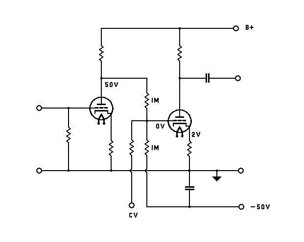
You can use another pentode as "dummy" tube to keep the current through the plate resistor constant and eliminate the thump. You'll still need to match the tubes for plate and screen current. With couple small changes you can make a compressor from the schematic below. If you match the tubes well it wont thump much and it'll have plenty of 2nd harmonic distortion. Signal on the control grid is largest at deep gain reduction and with large signals it'll distort like crazy.

You can use another pentode as "dummy" tube to keep the current through the plate resistor constant and eliminate the thump. You'll still need to match the tubes for plate and screen current. With couple small changes you can make a compressor from the schematic below. If you match the tubes well it wont thump much and it'll have plenty of 2nd harmonic distortion. Signal on the control grid is largest at deep gain reduction and with large signals it'll distort like crazy.

merlin
Well-known member
- Joined
- Aug 17, 2011
- Messages
- 380
You mean the thump in the first tube would cancel the thump in the second tube? I can see that working better in theory than in practice.DaveP said:I'm not thinking of a matched pair in push-pull, I'm thinking about a pair in series with two small gain reductions on each tube.
Then neither will partition noise be a problem.Microphonics will not be such a problem at line level.
DaveP said:Microphonics will not be such a problem at line level.
It was a big problem with the bunch of 6AS6 tubes I have.
It was a big problem with the bunch of 6AS6 tubes I have.
Maybe I should try the 5725 or 6187 which are the special quality Mil spec versions.
Incidentally, I first used the suppressor grid for compression in the Gates 28 CO I built a while back.
http://groupdiy.com/index.php?topic=53813.0
It was on the 6J7's and seemed to work fine with them
Best
DaveP.
Similar threads
- Replies
- 73
- Views
- 5K
- Replies
- 1
- Views
- 332


