Joemeek JM27 rebuild

GroupDIY Audio Forum

Help Support GroupDIY Audio Forum:

This site may earn a commission from merchant affiliate links, including eBay, Amazon, and others.

RuudNL

Well-known member
Joined
Apr 26, 2009
Messages
3,116
Location
Haule / The Netherlands
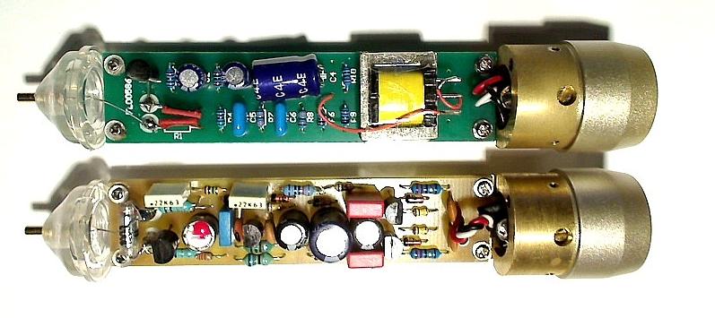
This week we got a couple of Joemeek JM27 microphones in.
Capsules are not too bad, but the microphones are noisy as h*ll...
Very simple electronics, single FET and a small (transistor radio?) 2:1 transformer.
Polarisation voltage was low, only 30 V or so.
So we removed the original PCB and created a new circuit, with a DC/DC converter for the polarisation voltage.
The result: a very quiet microphone with a higher output.
In fact the microphones are usable now!

JM27.jpg
 
I used the well known Schoeps design; the circuit used in most Chinese LDC microphones.
The space in such a pencil microphone is limited, so it was a real challenge to fit everything on a board of 18 x 75 mm.

http://www.pa0nhc.nl/AudioTechniek/mxl990_sp1mods/Schema%20SP-1%20=%20MXL990.GIF

By the way: the ceramic capacitors are part of the DC/DC converter!
 
Great RuudNL! Do you used a single layer, hand etched PCB? Looks amazing!

Also, looking at your schematic, I see that you are using 470uf bypass capacitors, instead of the usual 100uf found in common shoeps variants. Have you found some advantage in using these 470uf caps?

Thank you, and best regards!

HL
 
The schematic is the generic Schoeps diagram as used by MXL (amongst others).
I have added it to just give an idea of the circuit. (Shot asked for it.)
However: there are a couple of errors.
The diodes between collector and emitter of the PNP transistors are zener diodes (6.2V)
Also I replaced R13+R14 with a 500 K.ohm cermet trimpot, to make the FET bias adjustable.
And Gus, of course you are right (as usual!), it is not the exact Schoeps SDC schematic, but more a "Schoeps-ish" circuit.
In my circuit there is also a zener at point "A",  in order to have a fixed voltage for the first stage.
But the zener produces a certain amount of noise, so I use a 560 Ohm / 470 uF RC filter go get a clean voltage for the FET stage.
I used 1/10 Watt resistors to save space...

This is the real Schoeps SDC circuit:

FFSSXS3I6W2PWOJ.MEDIUM.jpg
 

Latest posts

Back
Top