instrumentation diff amp as pickup pre amp (floating)

GroupDIY Audio Forum

Help Support GroupDIY Audio Forum:

This site may earn a commission from merchant affiliate links, including eBay, Amazon, and others.

sumsound

Member
Joined
Apr 17, 2005
Messages
7
Location
Santa Rosa
Hi I posted this at Head wize they dirrected me here, I just wanted some opinions. They already cleared up the need for some sort of ground refrence for the non-inverting input of the op amp if capacitively coupled.

I was wondering if anyone here has any experience with making a preamp for bass and guitar (any electromagnetic transducer).

I have an old Les paul Triumph recording bass, It has low impedance humbucking pickups. I don't have the old line matching transformer for using the bass with High impedance systems so I've been prototyping some pre-amp circuitry.

Currently I have my excessive preamp which seems to work well. I wanted to get some oppinions on it.

LOWZ.jpg


Instead of tying one end of the pickup to ground like most set ups do I decided to try using a Diff Amp configuration (Instrumentation Diffamp for this prototype). It picks up less hum than it ever had in passive mode (After grounging metal mouting brackets around pickups the previous person who worked on it didn't do this)

I am using 2 9V batteries for a dual rail power supply setup (I don't have the right kind of Jack right now so I use a DPDT switch to turn on and off the thing). Using some of the Good ole' Cheap TLO7X Op-Amps.

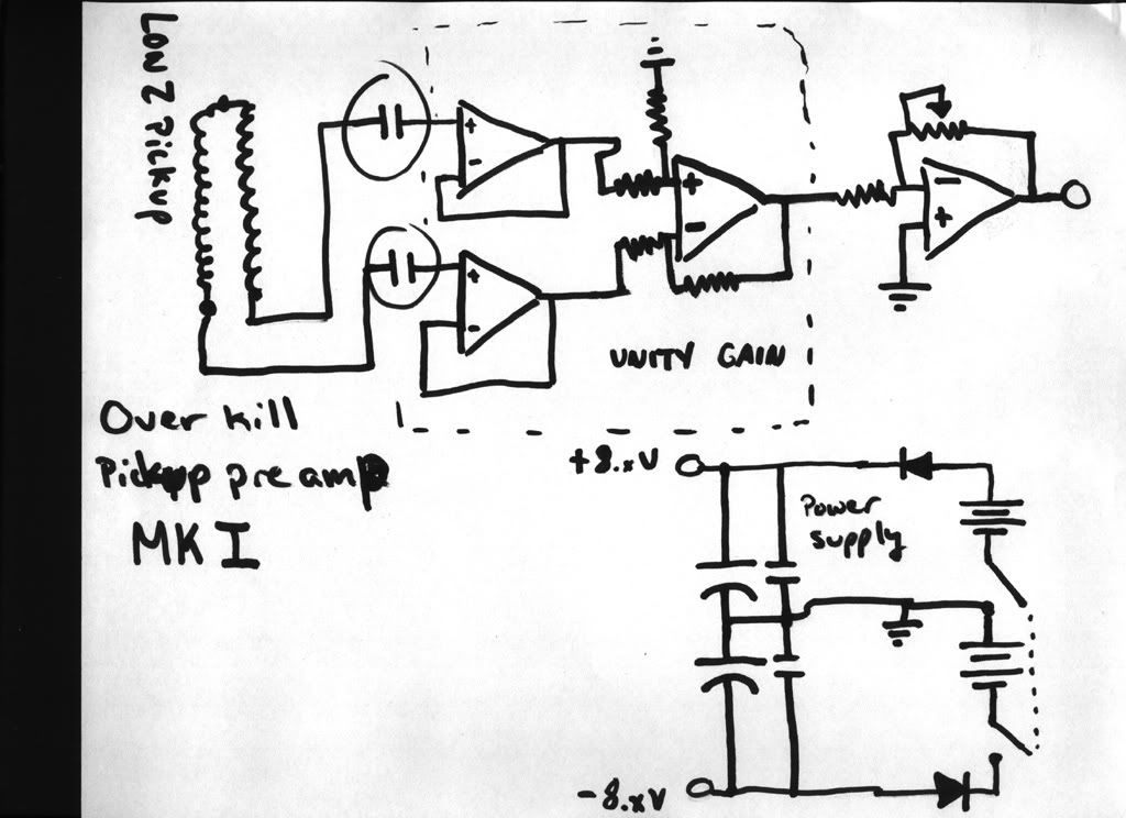
This is the basic preamp chain.
1: Non-Inverting, Unity Gain, Ultra High input impedance, instrumentation Buffers (Basicly 3 op amps for one buffer for each pickup. Total ground isolation).

2: Inverting Gain stage 1 per pickup -infinity to 26dB of gain currently TOO MUCH, I wasn't thinking and just figured a voltage gain of 20 would be fine. Sheesh I accidentaly blew out a speaker making my bass feed back.

3: Summing inverting op-amp to output.

I started building this preamp befor I read about A problem with impedance matching on Non-inverting ultrahigh input impedance op amps. Something about the Op-amp needing to see the same impedance at the inputs of both inverting and non inverting channel in order to reduce output errors. The pickups are really low imp like 150 to 200 ohms With multiple taps which make them go down to like 50 ohms.

Currently I just have the High imp (instrumentation) diff amps set at unity by tying the outputs to the non inverting inputs. I was wondering scince the Pickups are such low impedance if I would need to put like a 100 or 150 ohm resistor in between the Output and the inverting input of the op amp to simulate the pick up load?

I hope someone here knows what I'm talking about when I say instrumentation Diff. amp.

Thanks
Antone

P.S. I was thinking of cutting down on op-amps and just using a simple single op amp diff amp for the pickups (instead of the instrumention diff amp config). Anyone have any feelings or input about this?

Does anyone know how to make a 2nd or 4th degree Varriable Lowpass filter with resonance at the cutoff using only a stacked pot 2channel op amp and some Resistors and Caps. The low pass filter I have plenty of resources on. Its the resonace that baffels me. Ive seen very complex lowpass filter schematics with resonance. I have an Alembic bass with Anniversary electronics. It uses lowpass filters and I can flip a switch to turn on an 8dB resonant peak at filter cutoff, and It only uses one Opamp. Their next model has a tripple peak setting of 6dB 9dB and 12dB, and the really expensive system has one that has a continuously variable resonant peak from 0 to 16dB. And I think they only use one dual channel opamp per pickup. Any idea how they do that????

Sorry to be so long winded.

Antone.
 
This reference:

http://www.t-linespeakers.org/tech/filters/Sallen-Key.html

on Sallen-Key filters shows how to make the Q variable with a pot. If you want the gain to be independent of Q, use a unity-gain buffer tied to the inverting input, and take its output as the circuit output.

Or, if your following stage has high enough Zin relative to the potentiometer and feedback divider resistor, just run your signal out of the inverting input directly. Beware of capacitive loading!
 
Resonant low-pass 2-pole filter.

As bcarso says: muck with the Sallen-Key.

> Is the resonant cut off really that trivial, I've only seen very complex Synth circuits with resonance that tracks lowpass cutoffs. I've been searching!!!!

Resonance is defined by a number "Q". Q of about 1 gives a nice cut-off, Q of 0.5 gives a soft gentle droop, Q of 2 or more gives a distinct ring.

The 2-pole problem is trivial. Doing 4-pole with a wide range of frequency and Q is very hard work, and really only makes musical sense with synths, not traditional instruments.

"Equal Component Value Sallen-Key". Two resistors set the gain of an op-amp, which provides feedback to a 2-R 2-C network. For ease(?) of calculation, they normally use a parameter K instead of Q. I don't have the math in front of me. But roughly: if that op-amp is set for gain of 1, it is low-Q (soft cutoff), gain about 1.7(?) gives a Butterworth cutoff, and gain of 3 or more will actually oscillate. So "all" you do is set things up so that amp's gain can be varied from 1 to about 2.9. Slight trick is to adjust the filter gain without changing the signal gain, couple ways to do that.

After some thought (along the lines bcarso hints at), I decided to take the output from opamp with gain fixed at slightly less than 3 (3 or more will oscillate) and derive the filter feedback from a pot. But I wuz wondering how much the Q-pot changes the response. If you use 100K frequency pots, turned-down to 10K, with a 5K Q pot: hardly at all:

bass-vari-Q-sch.gif


For Freq-pot of 100K and 10K, R6 swept, you get these plots:

bass-vari-Q.gif


I suspect the "100K variable" could be a 100K pot plus a 2K series resistor. The highest cut-off would be ~4KHz, ample for 'lectric bass. Up there the response will not peak so much, but you don't want to out-screech the lead guitar anyway. Bumps at 1KHz-2KHz will peak-up the "top" of an electric bass just fine. At the other extreme, a bump at 80Hz will give "subsonic" bass lines: all the balls a speaker can manage, but nearly-no output in the lead-instrument range above 250Hz.
 
Good idea PRR. I shall store that one away, memory permitting.

FWIW the equation for the traditional equal R equal C with feedback C directly from the output is

Av = 3 - (1/Q); so for butterworth Q of .707, the gain is 3 - 1.414, or 1.585.
 
Thanks a lot guys

Thats some good stuff!!

All I could find where fancy discrete componant Synth filter schematics with voltage controlled resonance.
 
Antone I didn't have the time to get into the details of your other questions regarding the preamp. But I did want to mention that the issue of same-value R's is not important for FET input amps like the TL07X types.

The idea is that for amps that have a fair amount of bias current, like 5532's for example, if you want low d.c. offset you put similar equivalent resistances in the circuit for each input. The 07X series has very small bias currents flowing out of the inputs under normal conditions and they don't require this matching.

The idea of doing this has gotten taught a lot and sometimes without people understanding the rationale, so you will see an extra resistor sometimes even used with FET input amps. I made the mistake of pointing out a superfluous resistor to a past president of the AES, who was not a circuit designer but who had decided to make his own mic preamp. I said it was a common error, and I got a response to suggest that anything this guy did could NOT be common...

Having said that though, the 07X series has the advantage of low power consumption as well. But they are pretty noisy and not a very good choice in that regard for a low-Z pickup. Also, doing the in amp config the way you show is not the optimal one for noise either: Each of the unity-gain followers would be good for buffering high source impedances, and handling large voltages. But your Z is low, and your voltages are small, so one would use a configuration with some gain: see for example figure 4 of this ref:

http://ww1.microchip.com/downloads/en/AppNotes/00694a.pdf

So you could get your gain with the setting of Rf and Rg, use the third amp as unity differential gain like you do now, and dispense with the last amp in your schematic. Adjust gain with Rg.

I wouldn't probably bother with the coupling caps---you won't get much d.c through the pickup even with bipolar input amps. You still need some ground referencing resistors from each noninverting input to common---100k's ought to be plenty low enough.
 
> I shall store that one away

It has an elegance I didn't understand at first.

As you see, the high-Q curves are not hurt by the Q-pot; the error is in the low-Q curves.

Duh! At high-Q, the pot is mostly out of circuit.

The low-Q curves are skewed, but they are very gentle. The practical effect is a slight shift of the apparent cut-off frequency, which is a hazy thing anyway on such gentle curves.

It looks like you could save some parts. "Obviously" the Q-pot could be the upper resistor of the gain-set (R3). But pots are +/-30% tolerance, and we need like 10% precision in gain-set or there is a good chance some samples will squeal full-power when cranked to max Q.

R12 could be a short. Then lowest Q is 0.33, "resonant peak" is -9.5dB. But then the lower half of the Q-pot range covers a lot of super-gentle slow-rolloff curves, Q=0.33-0.7, that are perhaps not musically interesting. Or not to a guy who wants 9dB-12dB bumps some days. All the fun action is in the upper end of the Q-pot, effective gains more than unity. If you are into gentle slopes you should reduce R12... that 4K was just a wild stab.

Hmmmm.... lucky guess? Looks like with that value, the "0dB at cutoff" or "1dB bump Chevyshev" response is at mid-rotation. Butterworth is nice math and good summing, but 1dB bump is a nice band-limit function. Resonant gain drops to -5dB at the low end, +12dB at the high end of the pot. The spread from 6dB to 12dB of peaking is spread out over about 20% of rotation, 3dB per mark (assuming 0-10 marking), a managable curve.

For very extreme Qs, the Q-pot should maybe be inverse-logish taper, but at these "small" Qs of up to 4, the straight linear is best. You could load it a bit and spread the high-end a bit, but I suspect that if you want more than 6dB or so of peaking, you want it "all", at least on an instrument FX box.
 
PRR what program did you use to generate those graphs.

Are R1 and R2's (which would be a stacked pot) values going to interact with how the Q pot and resistor R6 and R12, I'm having a hard time wrapping my head around how that interacts with the rest of the filter.

I know if the Q section wasn't there I could season R1,R2 and C1,C2 to taste as long as they are equal values.

How does setting the gain to 2.7 affect the Dampening factor, I know the normal Dampaning factor for a 2nd order butterworth should Be 1.414 R3/R4 would be .586. This is of course 1.7 which give DF of .3 Does that change the filter type?

Oh wow you posted some more!!! I was just going back for notes.
You guys have been more than helpful!!!
 
bcarso

I guess I could just use a rheostat for Rg? But I'd never get below unity if I wanted to turn the pickup down.

I'm probably going to get rid of the buffers because I'd imagine the more devices in the chain the more noise and error they contribute to the circuit. I'm going to be summing the pickups in some form down the line.

Can you recomend some nice low noise op amps for my project, I'm using the TL07X's cause they are cheeeeeep. My Alembic uses I belive something like a TL2XXX something, some sort of rail to rail low voltage op-amp are those anybetter? Slewrate/power bandwidth probably isn't an issue at the voltage and frequencies I'm working at? I don't know if I can shell out the cash for any of the magic Burr Brown opamps (OPA627?) maybe some 13X's.

I was just thinking of going from
single op amp diffamp
to either Filter to gain
or Gain to Filter
Then to a suming either simple resistor or inverting summing amp.

Times fun when your having flys
:thumb:
 
For that source Z I'd use a 5532 or LM833. They will pull your batteries down faster though.

Do you really need attentuation? If so, make the difference amp less than unity gain and make up for it with Rg.
 
> I could just use a rheostat for Rg?

A Potentiometer, not a Rheostat.

The pot will let you adjust gain to zero, but more important: a siple rheostat in series with the 100K frequency-set resistor won't change the gain as much as the frequency. A low-value pot, say 5K, will add no more than 1.25K of source resistance, negligible upset of frequency except at the highest freq (lowest resistance) setting.

> the issue of same-value R's is not important for FET input amps like the TL07X types.

I thought he meant the fact that the 4-R 1-opamp "differential amp" is sensitive to source impedance unbalance. But in this case, the source is probably full-floating and within a few inches of the preamp, no problem.

Yes, balancing out DC bias-current error is a non-issue for FET amps at temperatures a musician can work in. (Up above 100 deg C it can start to matter...)

The TL072, despite being the oldest opamp in common (VERY common) use, is still the go-to device for guitar work. Easy to feed, very tame, plenty of bandwidth and slew, lovely hi-hi-Z inputs, and available almost anywhere four for a buck ($1.99/each at Radio Shack).

Other chips may be marginally "better" in some way, but rarely enough to notice. When you find something else in a mass-produced guitar pedal, it was probably a half-cent cheaper in large quantities.

Two flaws of the TL072 don't matter for guitar work. Input voltage noise is high, 2uV. But a standard guitar pickup's self-noise is about this size, maybe more after the volume/tone controls in the guitar body. TL072 does not like to drive loads lower than 2K, but guitar work is all 50K stuff. (In essence, the TL072 is no worse than, and somewhat better than, a 12AX7, the canonical guitar amp device, which guitars were designed to work with)

One exception: you say you have a special rare low-Z pickup. It is probably made to go into a low-Z Mike input. It probably has self-noise lower than a 12AX7 or TL072. In the original gig, Les would be driving a 12AX7 or similar through a 1:10 (200Ω:20KΩ) input transformer, to reject line-buzz and to trade voltage/current for best result with a tube grid.

For general use of this pickup with standard instrument amps, I would still use the ready-made low-Z/hi-Z transformer I mentioned in the other thread, or build around something better (Jensen and others will sell you very fine mike step-up iron). Toys like filters can be used with ANY bass, I don't think it would be smart to build one JUST for the Les Paul Recording Bass. Adapt the LPRB to hi-Z 1/4" output: there are a LOT more 1/4" basses and bass-toys around to mix-and-match.
 
I have a huge cavity that I can fit lots of junk into for the less paul.
The reason I wan't to have the filters in my less, like in my alembic. Is when you sum the pickups even if you have the good ole treble and bass boost/cut.

You get a lot of overlap in the Neck and bridge pickup outs plus if you don't have them buffered from each other it causes the pickups to load each other.

When each pickup is buffered and has its own filter I can do cool stuff like use the neck pickup for mostly just bass to low mid, and run the bridge for full. I was even considering using a Highpass for the bridge that tracked the low pass for the neck but I don't know If that'd actualy sound very good. It would be tough to do that with an external filter unless I ran stereo out, or had two XLR's to an external filter stage, than a summing stage. That seems less practical. Than doing it all internaly.

I'm suprised that not more basses are using variable lowpass filters, instead of Yea old tone controls and what I think of as lame blend controls. They work really well.

One thing that drives me crazy is the active systems that put the volume pot before the buffer. Whats the point? The pickup tone is going to change when you turn the pot down. I thought the point of active was to keep the load on the pick up constant so its resonant voice won't change.

Anyhow you guys are way above and beyond helpful.

I only hope I find a job in the electronics field before I forget everything I've learned (wishful thinking North Californias tech industry is doomed).
 

Latest posts

Back
Top