


Came across a slick way to make it easy to swap out key components when testing circuits/new designs. Thought I'd pass it along.
I've tried a number of ways to do this, with all the usual temporary component mounts/fixtures (screw down terminals, IC pins, etc). They often work. But sometimes - especially with PCBs - they're clunky or won't work at all, depending on the layout, through-hole location(s), etc.
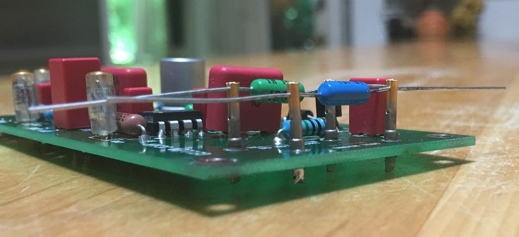
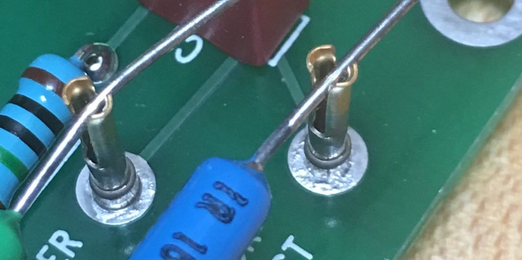
Female D-sub connector pins have split shafts that allow expansion for the male prong (keep it clean, now). The solder type (as opposed to the crimp-end type) have straight shafts that will fit many sizes of through holes, depending on the pin density of the D-sub connector they were designed for (from 0.38mm up to 3.81mm). Soldered into PCB though holes, two of these pins make a nice, quick-change component mount. The length may create problems of RFI pickup in some circuits, but for many situations they can work with no problems.
Not a universal solution, but definitely another arrow in the quiver.
Mouser part # 571-665693. Datasheet there shows various sizes, although they aren't all available through Mouser.
Pics to show what I mean:
BT
I've tried a number of ways to do this, with all the usual temporary component mounts/fixtures (screw down terminals, IC pins, etc). They often work. But sometimes - especially with PCBs - they're clunky or won't work at all, depending on the layout, through-hole location(s), etc.
Female D-sub connector pins have split shafts that allow expansion for the male prong (keep it clean, now). The solder type (as opposed to the crimp-end type) have straight shafts that will fit many sizes of through holes, depending on the pin density of the D-sub connector they were designed for (from 0.38mm up to 3.81mm). Soldered into PCB though holes, two of these pins make a nice, quick-change component mount. The length may create problems of RFI pickup in some circuits, but for many situations they can work with no problems.
Not a universal solution, but definitely another arrow in the quiver.
Mouser part # 571-665693. Datasheet there shows various sizes, although they aren't all available through Mouser.
Pics to show what I mean:
BT