How does this var resistor balance CMRR?

GroupDIY Audio Forum

Help Support GroupDIY Audio Forum:

This site may earn a commission from merchant affiliate links, including eBay, Amazon, and others.

boji

Well-known member
Joined
Jan 6, 2010
Messages
2,377
Location
Maryland, USA
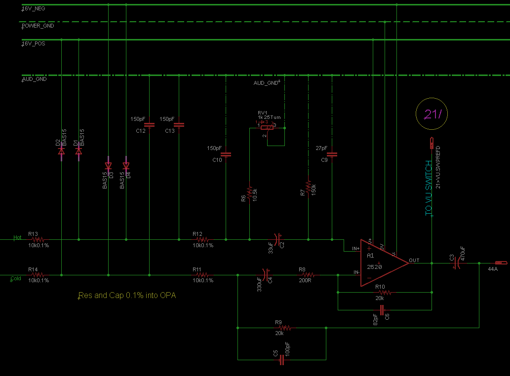
I know what to do to compensate for cmrr but I'm frankly a bit confused how it does it in the provided drawing.

I don't see a resistance equivalency on the cold leg wrt to  R6 10.5k + RV1 1k trim.  It looks more like a gain trim to me.  ::)  Anyone care to shed light on it?

I'll take an ignorant guess that the balance is coming from R10 + R 9 (10k) + R8?.

Thanks in advance for helping.

aEjngkp.png
 
Yep, you got it right. CMR is set by R6+RV1 (and I suppose R6+RV1 // R7) being equal to the equivalent resistance of R8, R9 and R10.

I do think, though, you'd also want a capacitor in parallel with R6 and RV1 equal to the equivalent  feedback capacitor.

I think if you're only using it as a BTA you could reduce it to six resistors and six capacitors.  Less if you omit the filter.
 
Sure a brain-pain.

If everything were perfect, RV1 should be 237 Ohms.

A 1K pot gives reasonable leeway for slop.

 
If I'm looking at it right, it should be --

(10.5k + RV1)//150k = (20k+200)//(20k)

I get RV1 = 271 and change.
 
> ..but why 0.1% (expensive) resistors then..?

Only the input resistors?

The 10K and 20K from output and ground are not marked for precision.

It is a real mess with 200r and 150K stuck here and there. While it could be done all with 0.1% and get ~~60dB CMRR untrimmed, it would require some very odd value somewhere. I wonder if they got one box of 10K 0.1%, maybe surplus, and improvised around that.
 
If you look at the original 528 input circuit the only reason it is so complicated is because the op amp is shared as a balanced transformerless input and a mic preamp. The 200R sets the maximum gain for the preamp to 40dB and I think the 150k is the load resistor for the input transformer.

I think given the whole original schematic the solution is elegant.

If you're only using the op amp as a balanced input, it seems to me that you would be better off simplifying it. But I could be completely off on my understanding.
 
> the original 528 ... shared as a balanced transformerless input and a mic preamp

I did not know where this came from. I wish boji had mentioned it.
 
gyraf said:
..but why 0.1% (expensive) resistors then..?

And some caps are also 0.1% .  :eek:

In API528c schematic I have, resistors are 1% and caps are mostly 2%.
 

Attachments

  • caps01.png
    caps01.png
    5.7 KB · Views: 11
If you're only using the op amp as a balanced input, it seems to me that you would be better off simplifying it. But I could be completely off on my understanding.

No, you're on point, dogears.  Using the 528 as the front end was originally meant for mic/line flexibility.  Additionally I did not deviate from the original schema since I had no hardware or experience in design.  As the project progressed, I decided to go with  500 slots for micpres, and added some relays to isolate A1 (independent of A2/fader) at the patch, essentially doubling mic channels if needed. Typically it will only act as a line driver, fed from daw.

Yeah no 0.1% caps once I saw the costs.

.but why 0.1% (expensive) resistors then..?
In a word, ignorance. Schema asked for 1%.

Thanks everyone!  I learn a little more every post.

Edit: I  can also chalk it up to serious mission creep.
 
Back
Top