Behringer ADA8000 pre bypass questions

GroupDIY Audio Forum

Help Support GroupDIY Audio Forum:

This site may earn a commission from merchant affiliate links, including eBay, Amazon, and others.
our recording path looks fine; for playback jitter will be lower if you let the Apogee be master

Well, The Apogee DA-16 need to be clocked because don´t have its own clock! :)

I know the importance of jitter in AD stages, thats why I use the ADC internal clock for recording.

Synthi
 
[quote author="synthi"]I know the importance of jitter in AD stages, thats why I use the ADC internal clock for recording.[/quote]

Can RME-cards handle two different clocks for recording and playback the same time?
 
[quote author="TobWen"][About RME and clock noise]
They do? I always thought, they're one of the bests?![/quote]
It's all relative.

RME's clocking made its claim to fame in the MADI arena, where their solution would bring digital streams with severe jitter (tens of ns) down to a much more manageable level (a few ns). For their SteadyClock technology they claim ~700ps jitter, which is much better than many other prosumer devices, although not as good as some of the newer offerings by Apogee et al. Then again, a $10 DIY word clock generator is likely to have an order of magnitude less jitter.

In the end, how much does it all matter? As the OPTOREC datasheets show, common ADAT receivers have ~1ns jitter. Most S/PDIF receivers have 100-200ps jitter, and that's without TOSLINK dispersion effects. All physically realizable wordclock-receivers will have some self noise, so even if a WC transmitter were to have zero output jitter, there will be some jitter by the time the reconstructed WC signal is applied to a PLL. Plus, as discussed before you'd never want to slave your converters to any incoming signal anyway, so that ~700ps jitter is likely 'good enough'.

[quote author="synthi"][quote author="jdbakker"]Your recording path looks fine; for playback jitter will be lower if you let the Apogee be master[/quote]
Well, The Apogee DA-16 need to be clocked because don´t have its own clock! :)[/quote]
Duh, yes. I'd overlooked that, sorry.

[quote author="TobWen"]@jdbakker:
So what do you think of hooking up a CS5361 with a Tent-clock and sending the data to an OPTOGEN?[/quote]
I would use a CS5381 or a PCM4222 myself. Have a look at this thread if you haven't already.

JDB.
[I should really find the time to get some results from my CS5381 board and post them, even if the rest of the recorder is still waiting for parts]
 
I didn't draw all the parts and connections, since I don't have software on this computer. So don't laugh, I had to use a demo-version of sPlan :)

In my opinion, this should be a low-jitter solution for the ADC and ADAT-OptoGen. Simple and effective.

I've also designed a high-quality input-buffer, which I will share for DIY in the next days (have to finish some exames).

This is for 44.1 kHz, since I don't work in other frequencies.
Of course, you can hook up another TENT-clock for 48 kHz and switch between them.

It wasn't possible to use 22.5792 MHz and MDIV (high), since TENT doesn't have these XOs :-((

JDB - what do you think?

K3S.gif
 
you guys loose me when it gets technical!!!

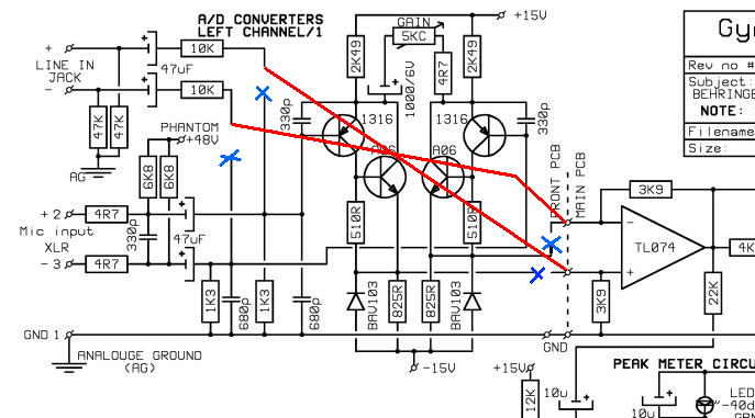
so i just went for the simple and probably wrong mod. all i wanted was the ad converter to run my pres into. soooo, i took the lot apart, slipped the xlr pcb out of its bracket and had a bit of a look.

from the xlr pads it goes to some wee smd things, so out with the electric desolder pump and away with them, one each on pins 2 and 3. then theres the five wires coming from the main pcb to the xlr pcb, snipped the red one and the one next to it.

now out with the solder iron and heat the xlr pads on 2 & 3, when the solders flowing push a 1K resistor through it and let that set, then connect the red wire to pin 3 resistor and the black one to pin 2 resistor.

i have a few of these units, so i took my cable tester with test tone in it and measured the input at its -10 and +4 settings with the level pot all the way down on a stock unit compared to the modded unit.

the modded unit is just a little hotter, so maybe a 1.2K resistor would be better.

the signal and clip leds both still work, and audio soulded fine.

is this ok to do to bypass the pre/line section to just use the ad's?

Iain
 
bigger resistors needed, tried to use rmaa to see whats happening on a loopback test but the out is way too hot for the input.

think its 5-6db up so i suppose i raise the resistors to about 2.5-3K ish. tis an excuse for a tinker :grin:
 
Hello guys,

this is my very first post, I'm definitely new to DIY really, I mean the more I've done so far has been modify an SM57 (transformer removal) and not much more.

I got the ADA8000 and I was trying to figure out how to the preamp bypass mod myself, to be more specific I was going for this one:

ad8kmod.jpg


but I opened the machine and I can't figure out what to do really, I have no one here that could do the mod for me and I could really use some help.

I took some pictures of the inside and if someone could highlight for me what exactly I should do that'd be much appreciated :)

pictures are not exactly high quality but maybe some of you already performed the mod

2810091908.jpg


2810091909.jpg


2810091921.jpg


2810091922.jpg


I know the 3d is old but I thought was better here than opening another one on the same subject.

Thank you in advance to everyone who'll chime in!

 
OK! Here is what I did to the ADA8000 preamp removal and mod.
The result are much more detail and better headroom.......... if my ears are correct!
1, completely removed the front end PCB
2, added XLR socket to the faceplate
3, added 100K resistor to ground on pin 2 and 3 of XLR
4, added Vintage WIMA cap then a 1K resistor
5, connect pin 1 to + input pin 2 to - input on second PCB socket
6, the pin3 is audio ground , pin 4 is SIG led , Pin 5 is CLIP led
7, Swaped out all the TL074 to MC33079
now here is some picts of what I did, still need to make it looks nice when I put it all back together
btw: those 22uf Caps that are in the signal path also need to be replaced next with much nicer caps or increase it to 100uf
ADA8K1.jpg

ADA8K2.jpg

Maybe I will put back a input VOL. Controll and a 1/4' input jack just to fill the hole back 8)
Comments are very welcome. Thank you all for the good info!
 
Back
Top