Behringer ADA8000 pre bypass questions

GroupDIY Audio Forum

Help Support GroupDIY Audio Forum:

This site may earn a commission from merchant affiliate links, including eBay, Amazon, and others.
[quote author="Kev"]The regulators are all very hot to the touch, too hot to hold your finger on, which is a concern that they do not have a lot of margin in their power supply. [/quote]

Turns out the problem is too much "margin" in the power supply! :grin:
 
As a ghetto recorder dude, who lustfully uses an ada8k and is gonna get another one, I do not need to hear bad news. :mad:

Carry on however.
If there is a Hifreq boost in there somewhere, let's smooth it out!

:Ron
 
[quote author="ask"]Thanks for the great clips. The result from (aligned) polarity(/phase) inversion is quite interesting. There is a lot more of a difference than I expected, however the difference sounds pretty decent.

Listening normal, the converted track has a sligthly brighter top end, and a lot more distortion on snare hits than the original. Makes me guess (wildly?) that the colouration comes from the analouge output section. Was it at 0dBFS?

[/quote]

I don't believe the files were near clipping... I would have paid attention to that. I do think the coloration comes from the analog stage, and that what I was interested in improving.

I submitted a poll on Gearslutz to see if others could hear the difference between a file converted once through these converters, then multiple times. http://www.gearslutz.com/board/showthread.php?t=98109&highlight=ada8000 The listeners did surprisingly well. I went back just recently, and listened again with fresh ears... I was easily able to pick the converted once file and converted 32x file in a blind test... which bothered me a bit.

Any other thoughts on simple analog stage improvements are welcome as I still own two boxes.

Oh... and I had yet ANOTHER box die on me. That's 2 of 4. I'm batting %50! Luckily this was within 15 days of purchase and GC exchanged my unit. So far no problems. My first one has been running for 6 months with no problems... go figure...
 
Cool test, thanks! Wanna hear it when I get home.

What I have in mind to mod is the analog circuit (have a better chip in place of TL074) and have a decent clock, the stock one scares me!

cheers,
Fabio
 
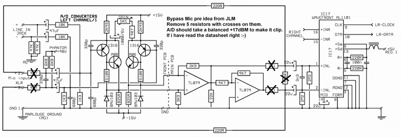
im gona regret this, but i want to bypass the whole analogue circuit on the way into the ada8000, build some greens or the like and just go straight in, been reading these pages and most of the meta on the ada800, but cant find any real simpleton info...

you guysare pretty smart, you start with a 'lets replace this bit' and end up with square wheels and smooth rides, i on the other hand tend to find myself 6 foot further back with frazzled hair and a shocked expression.

if i have missed the pages i need please direct me!!

yours with gratitude

Iain

the fool with a tool
 
[quote author="lofi"]im gona regret this, but i want to bypass the whole analogue circuit on the way into the ada8000, build some greens or the like and just go straight in, been reading these pages and most of the meta on the ada800, but cant find any real simpleton info...[/quote]
Page 3 of this thread, in the post by JLM Audio.

JDB.
 
[quote author="JLM Audio"]I

micprebypass.gif


www.jlmaudio.com[/quote]

i am having trouble with this!! to me it looks like i can wip out the front pannel and conect an xlr direct to the main board? cant be that simple can it? i use rme cards so digicheck tells me the input, is this for real?

i am flaberghasted if its that simple to get rid of the hellringer pres and replace them with something decent yet still use the ad's.

anybody tried this?
 
IIRC you can sever two wires for each channel on the connecting harness between front panel and main pcb, or remove the marked resistors and use the existing XLR jacks. It is a PITA to extract the front PCB from the front chassis, you have to remove two rubber strips, push all the phantom power switches down, break the glue holding the pcb in, and back the pcb away from the front so the pushbuttons clear, and slide it out the side. But you should be able to remove those resistors without doing all that.
 
i was thinking about rehousing everything into a 3 or 4U housing with 8 pres, or maybe just having it all on rear xlr's for in out and a blank facia, if your gonna do it, do it right as my mum says, do you know how big the smile on my face is right now?

Iain :grin: :grin:
 
not smiling now!! half striped, but cant find some of these resistors, damn surface mount stuff as well!!

on the bright side, i'm learning how to read schems a bit better :grin: :grin:

Iain
 
Interestingly the discrete preamp looks very similar to Phil Allison's one on Rod Elliot's site: http://sound.westhost.com/project66.htm
This configuration actually works very well.

I'd start at the power supply to reduce noise. Get rid of the 78/79 regulators on the +/-15V rails and replace them with something with much lower noise output (eg 317/337).
 
sorry to bore the gurus, but could anybody help me here, it a very nube question, and i promise if i ever get my head arround this stuff i will sit in the big chair, so please dont shout to loud or long :oops: :oops:

original scematic

http://www.gyraf.dk/schematics/Behringer_ada8000_analouge.PDF

[quote author="bitman"]

Hey Hey!

I just did this to one channel and it worked great!
I hooked up a high performance channel strip output though a
pair of 10k resistors to the inputs of the 1st tlo74 opamp.

When you open up the ada8000, you will see 8 cable harneses
with 5 wires each one red and 4 black. one for each channel.
With the ADA8000 knobs facing you, the left most red wire
is the + input to the tl084 opamp, the next wire to the right
of the red one is the minus input to the opamp. I cut both wires in the middle.

I soldered a 10k resistor to the red and black wire that lead to
the ADC/DAC board and wired my channel strip outputs hi and low
to the other leg of the 10 resistors.

W
LSB[/quote]

Why did he not recreate the input prior to the 10K resistors?

on the original schematic from Gyraph it shows the line coming in and going to earth via a 47K resistor, and on to a 47uf capacitor before the 10K resistors on both the +/-.

why has he missed these bits out? this is a quest for knowlage more than anything else. one of my ada8000 is in pieces on the kitchen table as i can follow the scem better this way :grin: :oops: :oops:

sorry

Iain
 
Hello,

I just modded one of my ada8000 converters.

on the first 2 channels I connected the converter input with a 10µF cap and a 220r resistor in series directly to the converter input all connections from the preamp were removed. so that's basicly the "jlm mod"...
I changed the smd 3n3 cap to a wima 4n7 as someone suggested here..

I used my rme multiface2 to playback the test signals

the measurements show a bit better result on the modded channels 1/2...
but all in all I can say that if there is an audible difference with or without the preamp it is extremely small...

http://www.cmaudio.de/ada8000/ada8000.htm

but what I found out is that the frequency response of the ad converter is not really flat in the higher frequencies... I made some measurements and there's not much differences between the input with and without the preamp.

here's a better pic of the freq response...
Spectrum.png


so do you think there's something more to improve, or do you have an idea what could be the reason for this unnormal frequency chart...?

cheers,
mat
 
That freq response looks equal to my first A/D-C prototypes.
The problem is that the analog A/D-section of the ADA8000 is way too simple ... LoFi.

I haven't got a ADA8000, neither the schematics.
I think, the ADA8000 has much potential and it would be easy to upgrade.
 
[quote author="TobWen"]I haven't got a ADA8000, neither the schematics.
I think, the ADA8000 has much potential and it would be easy to upgrade.[/quote]
Be our guest, the schematics are in the gmail-account of this nice group :thumb:
 
I have tried a few things and the difference is minimal. I tried keith's mod to the power supply. That's just insurance. I replaced the tl074 with an mc3079 on channels 1/2, and 3/4, and I replaced the 3300pf caps with 4700pf on chaqnnels 1/2, and 5/6. The cap swap seems to cut some high-end, whether it reduces the harsh/brittle sound, or dulls the sound, I don't know. The I.C. swap yielded no results to my ears. The change is not drastic. I need a sig gen to analize this more, and more time using it. I'm looking at this B'ringer Musician, the eight channel tube pre. Theres room in it to mount the back pcb of the ada8000. This uses four of the 2tube/2channel pcb assemblies, the same as in the stereo pre, and the stereo comp. I have addad high voltage to the stereo pre, and there is a noticable difference. although it may be less transparent, but it actually does something. So, I can run the magician on high voltage, and go directly to the A/D. So now I'm wondering how a better clock effects this box.
 
What's the current clock system? A xtal and divider or a PLL driven by an xtal or an external clock through a PLL?
It may be worth performing a jitter measurement on it to see if it really is a problem.
 
[quote author="gswan"]What's the current clock system? A xtal and divider or a PLL driven by an xtal or an external clock through a PLL?[/quote]
Four options: internal 12.288MHz or 11.2896 MHz Xtals for 48/44.1kHz,
or wordclock or optical in (ADAT).
Wordclock uses a 4046 PLL.

Schematics are in the GroupDIY Gmail account:

Go to http://www.gmail.com
Username: groupdiy
Password: thelab


It may be worth performing a jitter measurement on it to see if it really is a problem.
Would love to see the results of such a test :thumb:

One of the things I'm wondering is the difference between clock-performance of the Wordclock
vs syncing to the incoming ADAT-signal (I could in principle do either one when connecting the ADA8000 to my DAW).
My poor impression of the simple cheap 4046-PLL as used for the WordClock-section
may be completely unfounded.


Regards,

Peter
 
It's worse than that. The ADA8000 uses the AL1101 ADC and the AL1201 DAC, both from Wavefront Semiconductor. These chips are clocked at 48kHz (or whatever WC is), and use an internal PLL/synthesizer to generate a 64Fs(ADC) / 128Fs(DAC) converter clock. Based on the VERY wide capture range (=low-Q VCO tank) and the fact that they're using on-die passives for their clock generator I wouldn't be surprised if the converters added more jitter than that 4046.

Note that this also means that the jitter is only correlated between the two adjacent channels in a (stereo) ADC/DAC, as each of the eight converter chips has its own on-chip clock generator.

JD 'ick' B.
 
Back
Top