abbey road d enfer said:
The reason why there was a trim on Soundcraft's EBOS was that some early reviewers had noticed the signal was not identical in both legs, implicating the outputs were not truly balanced!
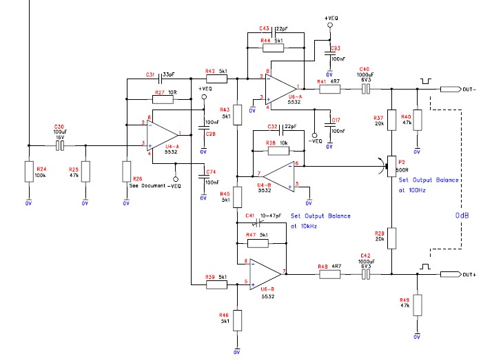
In fact, after trimming for equal levels, the impedance unbalance between legs was often even worse! But actual CMRR was not part of the final test prodedure, only zeroing the summed output legs via two 10k resistors.
Yes a mostly cosmetic issue that doesn't harm operational functionality. I recall seeing the trim on a highly regarded studio parametric EQ but thought (guessed) it was a tweak for CMRR not level match...
Since we can't control the impedance balance of the loads we see, you get what you get. Providing a static (moderate impedance) fixed termination helps apparent mismatches when driving high impedance terminations. I didn't do the bench work on this for Peavey, it was already a working circuit block when I got there, so I just used it as is (a benefit of working with other competent engineers). I saw the occasional level mismatch between output legs on the bench but just ignored it. I didn't ask who inspired them...
=====
I've told this story before but not recently... when the sundry IC manufacturers would bring their FAEs (field application engineers) to Meridian for a dog and pony show to pitch their new or soon to be new chips to win design-ins, they would ask us what we wanted (pretending to actually care :
")
). I still recall my wish list feature set for a universal output driver chip, some still unfulfilled, that I submitted to them for multiple years before they released their final parts.
#1 quiet turn on-off without pops and thumps... a lot of product design effort goes into this, especially for live sound reinforcement where thousands of watts can be banging speakers with those on/off transient events. Generally the noise bothers the customers more than damages speakers but keeping customers happy is important.
#2 ability to run driver output stage from hotter unregulated rails. More output is always better, so swinging to unregulated rails could buy a few extra volts of signal swing.
#3 voltage gain... no need for more signal swing if signal is already voltage limited by the path coming from the regulated rail powered circuitry, so at least a few dB of voltage gain on top of the +6dB gained from using two active outputs.
Thats all.... but the engineers were pretty much pimping their already finished silicon, not listening to me for things to change.
(In hindsight they were application engineers not chip design engineers, but then why ask?)
Back then without some compelling feature-benefit upgrade I was not motivated to pay more for a function we had already covered successfully for years.
JR
Caveat... I have not looked seriously at the modern offering of output driver ICs so can't say how current parts rate against my decades old wish list. They have hopefully gotten cheaper as more people use them in new designs.