efinque
Well-known member
- Joined
- Jan 3, 2018
- Messages
- 368
Sup GDIY,
just yesterday I started putting together a power amplifier.
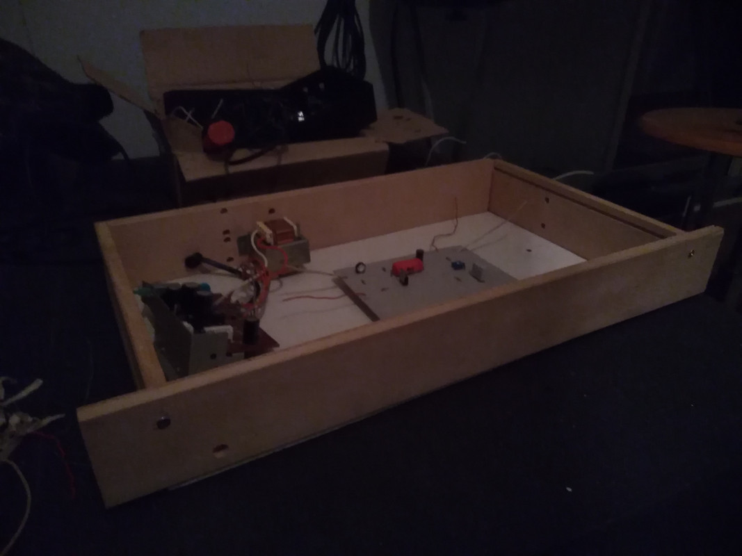
I've never built an amp before.. the design is based on a VCA/limiter from ESP. (I've built one for a crossover)
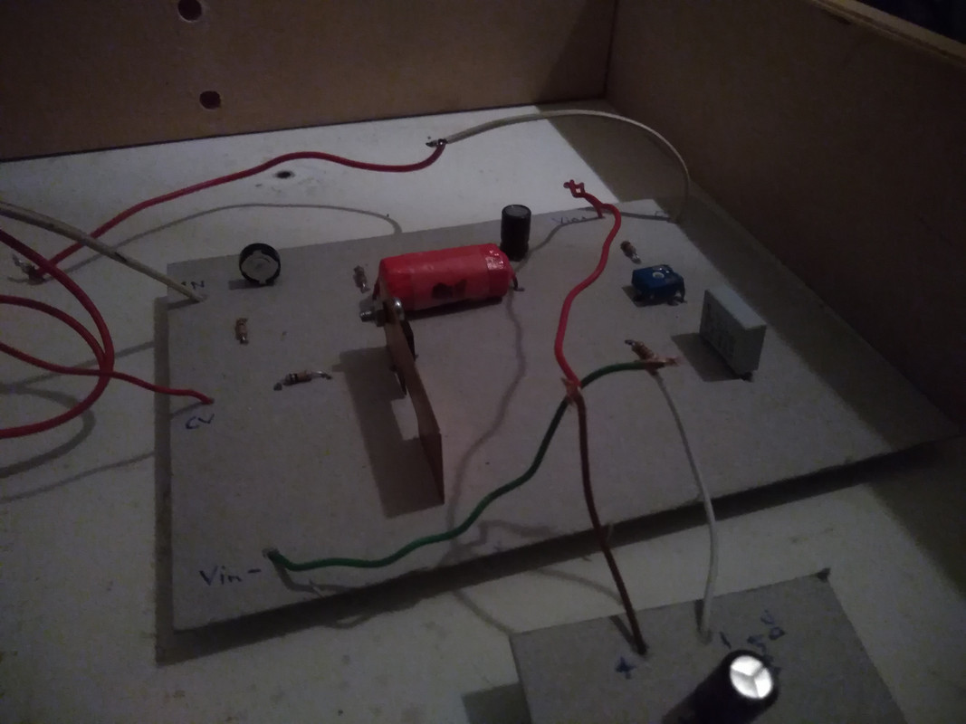
Technically it runs off a rectified ~38VDC PSU I pulled from a defunct Akai cassette deck ,the one I built earlier used a 12VDC wall wart. (edit : the transistor circuitry sees roughly a 24VDC voltage. I measured the signal inputs and outputs for leaks as well as the voltage applied to transistor drain, ideally I'm looking to either add another transistor for more gain and/or add another amplifier channel for stereo operation. It uses an IRF520 MOSFET, and slightly different components than the xover limiter, such as a homebrew cap and one from a hairdryer so it's mostly made from unobtainium/handwavium parts and as such almost impossible to clone)
I can't make a CAD drawing for the time being because my desktop PC is suffering from thermal breakdowns.
This is purely a test to see how a DIY amp would perform, and if it's worth the trouble (most cabinet builders use/buy off-the-shelf or custom it seems).
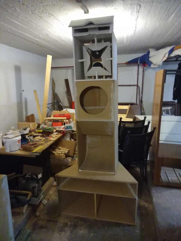
Essentially I'm looking to use them (and my earlier DJ mixer & crossover builds) in a PA system I've been building (it's still a work in progress, link to build thread in Speakerplans)
Any thoughts/advice/ideas?
-ef
EDIT : tested with a driver.. it works I guess. To clone it I'd need to reverse-engineer the PSU and find a similar cap to the one it has now, luckily I rolled those capacitors in pairs.. rest of the parts are off-the-shelf.
just yesterday I started putting together a power amplifier.
I've never built an amp before.. the design is based on a VCA/limiter from ESP. (I've built one for a crossover)
Technically it runs off a rectified ~38VDC PSU I pulled from a defunct Akai cassette deck ,the one I built earlier used a 12VDC wall wart. (edit : the transistor circuitry sees roughly a 24VDC voltage. I measured the signal inputs and outputs for leaks as well as the voltage applied to transistor drain, ideally I'm looking to either add another transistor for more gain and/or add another amplifier channel for stereo operation. It uses an IRF520 MOSFET, and slightly different components than the xover limiter, such as a homebrew cap and one from a hairdryer so it's mostly made from unobtainium/handwavium parts and as such almost impossible to clone)
I can't make a CAD drawing for the time being because my desktop PC is suffering from thermal breakdowns.
This is purely a test to see how a DIY amp would perform, and if it's worth the trouble (most cabinet builders use/buy off-the-shelf or custom it seems).
Essentially I'm looking to use them (and my earlier DJ mixer & crossover builds) in a PA system I've been building (it's still a work in progress, link to build thread in Speakerplans)
Any thoughts/advice/ideas?
-ef
EDIT : tested with a driver.. it works I guess. To clone it I'd need to reverse-engineer the PSU and find a similar cap to the one it has now, luckily I rolled those capacitors in pairs.. rest of the parts are off-the-shelf.