5v 5A psu

GroupDIY Audio Forum

Help Support GroupDIY Audio Forum:

This site may earn a commission from merchant affiliate links, including eBay, Amazon, and others.

salomonander

Well-known member
Joined
Aug 28, 2011
Messages
947
Hey,
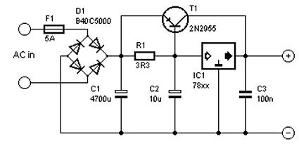
im really terrible at theory, so maybe someone can help me. I found this schematic for a 5v psu. The 78H05 is rated at 5A. Will the 2A 18v transformer deliver enough power for 5v 5A? Thanks
 

Attachments

  • PNG-Bild 2.png
    PNG-Bild 2.png
    111.1 KB
Yeah that regulator will have to shift a ton of heat with the large voltage drop , but you still have no where near the current capacity you need (5A), a 6-9 volt ac winding on a transformer with adequate capacity would be a better starting point . 
 
salomonander said:
Hey,
im really terrible at theory, so maybe someone can help me. I found this schematic for a 5v psu. The 78H05 is rated at 5A. Will the 2A 18v transformer deliver enough power for 5v 5A? Thanks
Definitely no. You can't miraculously get 5A DC from an 2A DC source. You must have a transformer that supplies the necessary current to start with.

And it should be the right voltage. Otherwise the regulator will have to dissipate that as heat. For example, 18V - 5V * 5A = 65W. If that thing isn't mounted on a block of aluminum the size of a book, it will probably start smoking.

Note that you can buy a 5V 5A SMPS for $15 that will be better than any linear supply in every way.
 
Replace the 7805 linear regulator with a switching one, your transformer is perfectly suited for that. Stick to the datasheet circuits for exact usage.

This one has a 5A maximum current, may be suitable or not, depends if you need those 5A only in peak situations or continuously.
This one has 8A maximum current. It is marked as obsolete, but Digikey still has 500 stock. The implementation is a bit more involved, I'd prefer the other one if 5A isn't absolutely necessary.
 
It's a simple linear psu so (as Squarewave says) you can't transform a 2A input current into 5A.
Basically you need to supply the output current and a bit more for circuit operation at the input.
And the voltage drop across the regulator x the current gives you heat (bad!).
Remember that the voltage at the regulatotr input will approximate to (1.414x18) - 1.4 so about 24V !!!
 
If you really want to go linear, this should give you 5A at 5V.

000033.gif

Source; Circuitsonline.net

So 78xx becomes 7805 and your transformer should be 6V~ secondary.

Or just get this and be done with it;
https://www.reichelt.nl/nl/nl/schakelvoeding-25w-5a-5v-snt-rs-25-5-p137084.html?PROVID=2809&gclid=Cj0KCQjw1a6EBhC0ARIsAOiTkrEZXUIcsdxw2p4VhtKtxAoBVVkbofQn9TG3jOSqJW2ynn6xxa1f1I0aArgOEALw_wcB

It's Meanwell, it's pretty decent.
 
Thanks a lot guys. You saved me a headache :) i really do not want a switching supply. All psus in my studio are none switching and as soon as i use any of these switching psus i get interference with pickups etc. thats why i want to build a proper one. Its really for usb devices mainly.

What would be the smarter option?
- use the circuit i found, but replace with a 6v 5A transformer and according rectifier
- use the circuit posted by PermO (thanks)

If they both work i tend towards the former option as i already bought the 78H05

Thanks a lot guys. Its much appreciated.
 
salomonander said:
What would be the smarter option?
- use the circuit i found, but replace with a 6v 5A transformer and according rectifier
- use the circuit posted by PermO (thanks)

If they both work i tend towards the former option as i already bought the 78H05

Thanks a lot guys. Its much appreciated.

Whichever way you go make sure to overdo the heatsinking. Are you familiar with thermal interface pads / grease etc ?
 
Newmarket said:
Whichever way you go make sure to overdo the heatsinking. Are you familiar with thermal interface pads / grease etc ?

Thanks. I know about heat dissipation- but maybe not enough? I would have mounted the 78H05 on a regular T0-3 heatsink with a mica insulator. But maybe thats not enough?
 
Yup, always overdo the heatsink, just to be save.

Also, will it be feeding one device ? or multiple devices ?
If you worry about clean power don't just ty a bunch of devices together at one PSU output.

Create multiple output tabs using a resistor and a small cap.

Or... take a bunch of 7805's to create multiple regulated tabs.
 
PermO said:
Yup, always overdo the heatsink, just to be save.

Also, will it be feeding one device ? or multiple devices ?
If you worry about clean power don't just ty a bunch of devices together at one PSU output.

Create multiple output tabs using a resistor and a small cap.

Or... take a bunch of 7805's to create multiple regulated tabs.

Thanks a lot. Creating multiple outputs.... what kind of resistor and cap values would i need? Can you help me out there? Because yes, i want to use this for a bunch of devices. Basically all my usb powered stuff. Maybe i can find a commercial usb hub that allows me to fit the caps and resistors directly to each usb outlet. Would that work?
I really appreciate your help!
 
Ok, now I would have to do an estimated guess as I am no expert on this  ;D

I'd say take a 47R resistor and a 1 - 10uF cap for each output.

If I wanted to have 5 outputs I would simply stick 5x 7805 on a chunky heatsink and have 5 regulated low current outputs.

There might be more elegant ways of doing this, I always go here; https://sound-au.com/ when I plan to build something.
 
Ive definately seen issues arise in pedal boards where multiple switchmode psu's cause a bad interaction in the signal path . In the context of USB , computer supplies are notoriously dirty and untrustworthy .
It seems like a good plan especially for a lot of the new audio devices that are USB powered to make a bit more effort with the supply and not rely on a switcher in a computer or even worse , a contagion of wall warts.

In terms of the transformer rating , if you want to be able to deliver the full 5V 5A DC you would choose a transformer and derate it by 50% to account for the AC current , so you want a 6v / 10A winding .

I see what helped confuse matters with your original schematic  , he's used a 220 volt transformer supplied with 110v ac , so he's going to see roughly half the expected 18 volts on the secondary winding .

https://www.ebay.ie/itm/184084516607

that one might do you , but dont forget to ask about mounting hardware .
 
Tubetec said:
Ive definately seen issues arise in pedal boards where multiple switchmode psu's cause a bad interaction in the signal path . In the context of USB , computer supplies are notoriously dirty and untrustworthy .
This has been discussed so many times I feed funny saying this but I'll do it anyway ...

1) Not all SMPS are good. SMPS noise is very dependent on layout and parts. But there are ones that are known to be good. In particular the MeanWell ones are popular. I once created a mic pre from an 48V SMPS for like $9 USD and it's noise floor completely flat and free of mains hum.

2) You must load an SMPS with at least 20% of the rated load or it will modulate the output at a low frequency. For smaller SMPS this frequently manifests itself as a whistle in the 1-3kHz range. For larger supplies, it can create massive noise at a wide range of frequencies. And note that at some point you can't just add a load resistor because it will need to be huge. So you need to pick an SMPS that supplies the right current to begin with. It should be selected for at 80% of load. SMPS work better when loaded. Even to 100%.

3) If you short an SMPS for even a few ms, the output protection mode (sometimes referred to "hiccup" mode in the datasheet) will kick resulting in only short bursts of output and generally not work at all. This is frequently caused by too much capacitance on the output such as when you connect the output directly to a board or multiple boards designed for a linear supply that have a lot of filter capacitors. The solution for this is to add a capacitance multiplier on the output of the SMPS. That will slowly turn on the pass transistor and let the filter caps charge up slowly and keep the SMPS output protection from kicking in. Note that for more than a few 100mA, a two transistor CM is required which incurs two diode drops in voltage but the larger SMPS frequently have a trim that can be adjusted upward to compensate (assuming you need the full voltage). You might need a largish capacitor directly on the output of the CM at the 0V reference where various grounds converge (sometimes referred to as the "star ground" but it's really more like the trunk of a tree).

4) You should filter the SMPS input too. The switching noise of an SMPS can easily go backward out the input and then pollute things connected to it. This is especially true of DCDC converters with similar frequencies where all of the inputs are connected together and cause low frequency "beating". If you look at datasheets, you can frequently find filters on inputs that are required to achieve a certain EMI rating. Althogh personally I have never experienced this kind of noise so this part is somewhat theoretical. I have used SMPS without input filters and never found them to pollute other devices. So it's not required. But line filters are pretty cheap so if you're designing something from scratch, you might as well.

5) At one point I was advocating CLC fitlers on outputs. But now I'm leaning toward just using capacitance multipliers which will filter out the high frequency switching noise and keep the output protection from kicking in as described above. You don't need a regulator since an SMPS is a regulator. Or, if you need to bring the voltage down a little, then use a regulator.

If one follows these rules, SMPS are superior to linear supplies in just about every category. The only potential issue would be that they can emit EMI that can be picked up by nearby devices like guitar pickups, high impedance / high gain devices or unshielded magnetics. But depending on the amount of current being switched, the device would have to be fairly close. For a typical SMPS of a few 100mA or so, it would have to be a few cm. Even for a 5A supply you would probably have to be standing right next to it. But again, not all SMPS are good. If it's just some crap wall wart from Ebay, you're on your own.

For a 5V 5A supply, an SMPS is definitely going to have superior noise performance to a linear supply. A linear supply is almost guaranteed to have mains hum. But again, there are rules for SMPS. If you're trying to mount it inside a tube amp, that would not be good.
 
Last edited:
Thanks a lot. I never expected so much information. Great. Ill start by getting the right transformer. Hammond makes a 6v 10A one that should do the job. Ill let you know, once im stuck during the build :)
 
Back
Top