3 way monitors from scratch.

GroupDIY Audio Forum

Help Support GroupDIY Audio Forum:

This site may earn a commission from merchant affiliate links, including eBay, Amazon, and others.

DaveP

Well-known member
Joined
Nov 8, 2005
Messages
3,185
Location
France
The last time I made speakers on the forum was  some Auratones, way back in 2011.
https://groupdiy.com/index.php?topic=43086.0

This will be way more challenging, but that's how we learn.  These will be passive units with  first order series crossovers.
I have wound some air coil inductors for nominal crossover frequencies of 500Hz and 5000Hz

I have some top end bass drivers from an old project that I will re-use, they are 8" Monacor SPH-200KE units.
https://www.monacor.com/products/components/speaker-technology/hi-fi-speakers/sph-200ke/
They only need a relatively small cabinet volume so they are ideal for monitors.  they will be around 20Litres.

The mid ranges are Monacor MSH-115's
https://www.monacor.com/products/components/speaker-technology/hi-fi-midrange-speakers/msh-115/
They have one of the flattest frequency responses I've seen and I have them in my hi-fi speakers too.

As discussed in the drawing board thread, the main problem is minimising diffraction effects in the mid- treble region.
https://groupdiy.com/index.php?topic=68928.0

If your monitors have excessive dips and peaks you can't be expected to hear the detail or EQ effectively.

If you wonder why I'm bothering with passive monitors, take a look at the electronic junk inside this active monitor.
Do I really want my sound going through all this crap?
https://www.youtube.com/watch?v=dftkoD7LG0A

DaveP
 
DaveP said:
  These will be passive units with  first order series crossovers.
Care to explain why? In my experience, 1st-order x-overs have the only advantage of having a virtually perfect transient response in one very small area. Actually they suffer severe lobing in the x-over region, that extends more than 2 octaves around the x-over frequency.
Low-order x-overs increase the constraints on transducers regarding their response beyond the intended range. This is less a problem with a 3-way design, though.
Series-connected x-overs are typically more complex than parallels, because the impedance of the transducers must be linearized, by the use of dual circuits (a dual is a circuit that cancels the reactive term in the circuit it complements).
My current professional activity is designing loudspeakers, although for PA applications. Although all FOH systems use active x-overs, for practical reasons, most floor monitors are passive.
I find much easier to design parallel Linkwitz-Riley 4th-order x-overs than anything else, because the transition zones are much narrower, which puts less constraints on the transducers response, and they result in less lobing.

If you wonder why I'm bothering with passive monitors, take a look at the electronic junk inside this active monitor.
Do I really want my sound going through all this crap?
I'm not an advocate of "less is best"; I think it takes what it takes to work. The difference between an active monitor and a passive one is that it has one more active x-over, one less passive x-over and one more alignment circuit.
Considering what a passive x-over does to the response of a transducer and the good an active alignment circuit does, no wonder most manufacturers chose the active way.
Now, as a DIY exercise, I probably would not choose to build an active monitor, because the optimization takes tools that are seldom available.
I must say I have seldom heard a better passive monitor than the 8" PBM2, with objective performance matching the subjective impression.
 
Care to explain why?
You can make a top quality tube Amp with 2xEF86 and 2xEL34/KT66, there are no 4 transistor Hi-Fi amps anywhere,  This tells me less is more for amplifiers.

There is an excellent analysis of series v parallel at  Elliott;s site :- http://sound.whsites.net/parallel-series.htm

The series network is probably a better choice than parallel for a number of reasons. It retains a flat response even when the driver characteristics change, and is to an extent 'self correcting'. Implementation is no more difficult than for an equivalent parallel network, and the same component values are used.

I made  series crossovers for my 40 Litre Hi Fi cabinets and they sound great, so I am making the choice from experience, but I will be testing the monitors as I do the project in any case.

For first order crossovers, the components need 2-3 octaves of response past the crossover.  so that needs good drivers and carefully chosen crossover frequencies, but it is do-able.  Ferrofluid drivers need less Zobel correction than standard drivers.

DaveP
 
DaveP said:
You can make a top quality tube Amp with 2xEF86 and 2xEL34/KT66, there are no 4 transistor Hi-Fi amps anywhere,  This tells me less is more for amplifiers.
Counting the number of active components in an electronic product makes sense only in the mktg dept. Does passing signal through a transformer helps performance?

There is an excellent analysis of series v parallel at  Elliott;s site :- http://sound.whsites.net/parallel-series.htm
This tells it all to me, as it coincides with my experience.  "with the (relatively) small difference of woofer back EMF applied to the tweeter. I know and can prove it's not a small difference.
Certainly, the parallel variant is easier to design, and this alone is probably a good reason to stay with a parallel crossover - and probably also explains why the vast majority of loudspeaker designers use parallel rather than series filters in commercial products." He forgets to mention the series arrangement has more losses, and requires the MF & HF inductors to be rated for the total power of the speaker, not only for that of the transducer they are driving.

For first order crossovers, the components need 2-3 octaves of response past the crossover.  so that needs good drivers and carefully chosen crossover frequencies, but it is do-able.
My main point is that the actual performance is not as good; the effect of lobing is that diffused energy is more variable than with higher-order x-overs. That counts even for proximity monitoring.

Ferrofluid drivers need less Zobel correction than standard drivers.
Zobel correction is about the same than a similar non-ferrofluid, since Zobel correction compensates for the voice-coil's inductance. What changes is the damping of the mechanical resonance. Linearizing the impedance around mechanical resonance involves an RLC series circuit. It may not be necessary if the actual x-over point is far above the mechanical resonance. And much less so in a parallel x-over arrangement.
The only case I had to use mech.resonance compensation is with coaxial speakers, where acoustic coupling between transducers is significant.
 
Does passing signal through a transformer help performance?
I think it does.  There would be absolutely no market for vintage recording gear containing input and output transformers if they were detrimental.  They may not measure so well with instrumentation test, but they confer a quality that pleases the ears, which are the final arbiters.

As series and parallel crossovers use the same value components, I will try them both and see if I can tell the difference, the problems you expect may not matter from a distance of one metre.

Thanks for your  comments

DaveP
 
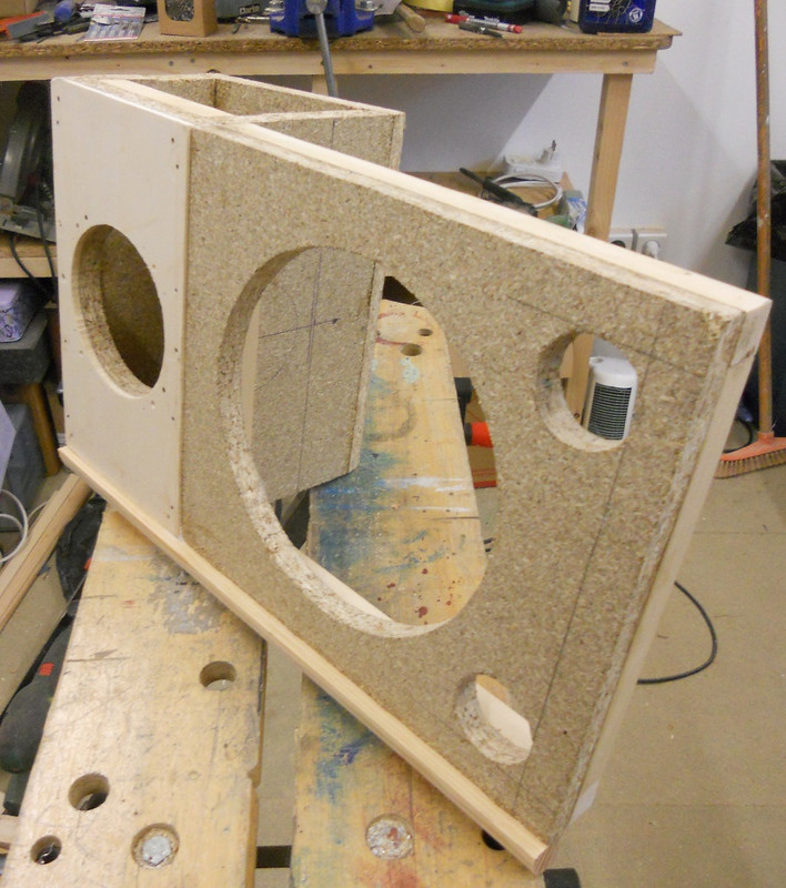
This gives a general view of the front baffle and the mid range box.  The drivers are all time aligned.  The bass is mounted on the outside surface then further thickness added until flush.  The corner radius will then be flush too.  Two small ports take up less room than one large one.

General1.jpg


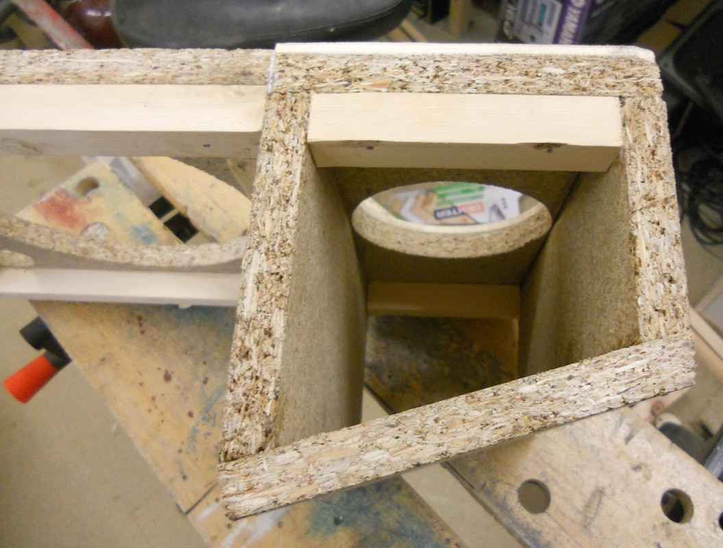
The mid range needs 2.4Litres but the exterior volume works out at 3.2 Litres, this volume has to be added to the volume required for the bass unit.  The back wall is angled to minimise reflections building up at any one wavelength.

mid_box1.jpg


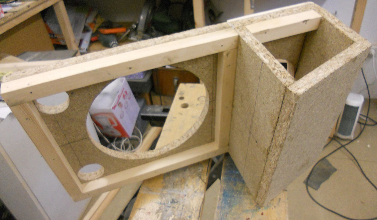
The interior timber corners add up to just under a litre and along with the volume of the bass unit, must be added to the internal volume.  The crossover will be mounted externally to avoid heating the interior and changing the performance of the drivers.

Back_view1.jpg


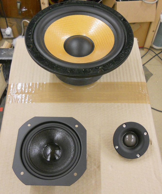
These are the drivers that I'm using
Drivers1.jpg


All for now
DaveP
 
DaveP said:
For first order crossovers, the components need 2-3 octaves of response past the crossover.  so that needs good drivers and carefully chosen crossover frequencies, but it is do-able.
Bozak Concert Grand's are "proof" that first order crossovers can work.
Rudy Van Gelder had a set in his living quarters above the studio.
 
gridcurrent said:
Bozak Concert Grand's are "proof" that first order crossovers can work.
What does "work" mean? Making some noise, no doubt. Apart from that, their fidelity is more that of a juke-box than that of a studio monitor. Read carefully
"https://www.stereophile.com/historical/1005bozak/index.html"
or, from Pinterest "The Bozak Concert Grand was a refrigerator-sized speaker system that contained four 12" woofers, eight tweeters and two 6" midrange drivers. The Concert Grand was designed to fill large spaces and were not at their best with listeners closer than 20 feet away."


Rudy Van Gelder had a set in his living quarters above the studio.
As Henri Mancini and Benny Goodman. Many famous "names" get to have equipment they have not paid for, given them by manufacturers hoping to capitalize on the connection. Apparently it seems to work.
 
Is the wood selected for any particular reason? Is that particle board
Yes, it's because it is non resonant and heavy, the last thing you want is something that is great for violins or guitars.

DaveP
 
In the course of preparing for the project I tested the T/S parameters of the bass drivers against the spec.  These are now around 8 years old but still going strong.  The spec was Fs 28Hz and Vas was 54Litres, my testing showed that they were well out of spec.

The surrounds are neoprene rubber which is used on the best speakers, foam surrounds often deteriorate over time.  I measured the temperature of the surround with an infrared thermometer as I warmed up my workshop and measured the resonant frequency at different temperatures.

30dbcia.jpg


You can see that the resonant frequency varies a lot with temperature so the stiffness reduces as it gets warmer.  This causes the Vas to reduce in proportion too.  I have a Vas test box and I found that Vas had changed from 54L down to 44 or 33L depending on temperature.  I'm reporting this in case you make your own speakers and wonder why the results are not as expected,

Despite this change I am still able to make these boxes a reasonable size and the WinISD programme indicates that a 24L to 25L box will give me 42Hz at -3dB (E on Bass guitar).  I was surprised to find that many studio monitors spec at 50 Hz.

The damping material used in speakers can ( if done correctly) reduce the speed of sound by around 10~15%, as far as I understand the mechanism, it slows the movement of sound waves through friction on the fibres.  This can apparently make a stuffed box appear about 10~15% larger than predicted. 

DaveP
 
DaveP said:
In the course of preparing for the project I tested the T/S parameters of the bass drivers against the spec.  These are now around 8 years old but still going strong.  The spec was Fs 28Hz and Vas was 54Litres, my testing showed that they were well out of spec.
A possible explanation would be that tne suspension has hardened. That would not be impossible since neoprene, like many petroleumderivatives, tends to vulcanize (a form of polymerization) over time

You can see that the resonant frequency varies a lot with temperature so the stiffness reduces as it gets warmer.  This causes the Vas to reduce in proportion too.  I have a Vas test box and I found that Vas had changed from 54L down to 44 or 33L depending on temperature.  I'm reporting this in case you make your own speakers and wonder why the results are not as expected,
It is a fact that variations of suspension compliance (and the correlated change in Vas) have a marginal effect on performance. We QC transducers when we receive them from the factory (PHL or B&C) and the deviation is quite large, often close to +/-8%. Since the resonant frequency varies according to the square root of compliance, and mass is extremely well controlled, that means that compliance can vary as much as +/-16% from sample to sample (so does Vas). The effect on the actual performance is negligible; they all pass final QC.

Despite this change I am still able to make these boxes a reasonable size and the WinISD programme indicates that a 24L to 25L box will give me 42Hz at -3dB (E on Bass guitar).  I was surprised to find that many studio monitors spec at 50 Hz.
I would think it's due to the more and more common trend of using subwoofers for the very low frequencies, even in studio monitoring.

The damping material used in speakers can ( if done correctly) reduce the speed of sound by around 10~15%, as far as I understand the mechanism, it slows the movement of sound waves through friction on the fibres.  This can apparently make a stuffed box appear about 10~15% larger than predicted. 
I have found that the actual volume ot the absorbing material defeats this virtual increase. However, not all damping materials are equal; in particular, the commonly used polyester fleece ("molleton" in french) is inefficient.
 
Rather than slope the back panel to stop a standing wave resonance returning through the back of the cone, I have a combined a sloped  side brace to do double duty.

i20nqu.jpg


The structure is now complete, the sides will be finished with plywood so the radiused corners will be a flush fit.

ajuy2s.jpg


The front panel will have two layers of plywood to make the bass driver a flush fit.  The mid-range will have a 4mm black wool felt surround to absorb reflections.

xehbpx.jpg


The tweeter will be mounted in this housing on the top, this should avoid the diffraction  effects that occur when putting a tweeter in a cabinet and make it easier to time-align.

biqg08.jpg


DaveP
 
On some particle board, I marked out the circle for the tweeter to pass through, then I drew the outer circle to fit inside the shell.

Some very careful jigsawing gave me the rings which were glued in place with  PVA,  They are very tight and will never come out.

I just have to make some brackets and solder on the new leads.

oojzb.jpg


DaveP
 
And then there were two...................

xp0zd3.jpg


The second one was easier to make after the first one was sorted out.

The gaps between the surface and the corner radius will be filled by a first layer of 2mm cardboard followed by 5mm plywood to bring it flush to the surface.

The change in materials makes it more difficult for vibrations to travel through and damps the panels.

a1sox3.jpg


I will cover the mid-range panel with 4mm  wool felt.  This stops reflections from the speaker cone to the baffle arriving after the event and blurring the sound image.

The length of the reflex tubes will have to be decided after testing.  The simulations indicate 17~22 cms,  but I will try to test the performance to find the optimum length.  As the lowest note I need to reproduce is probably 42 Hz, I may check which length gives me the highest output at that frequency.  There are so many variables in a project like this that it is asking too much of a simulation to provide accurate results.

DaveP
 
Yes, I have a Bosch electric hand-held sander with coarse grit paper, that's all.

Two quadrants butt up tight and one overshoots, then you cut the excess of with a saw and sand the rest, following the radius from the three sides, it takes about one minute per corner.

DaveP
 
The cardboard arrived today.

6gvew2.jpg


Don't want it solid with glue.

289c3yd.jpg


Card in place and glued for plywood

34ns0nm.jpg


Finished Panel ready for weights

jhfngj.jpg


I will have to put these old transformers on Ebay, but at the moment they are being useful!

20thz6q.jpg


This thicker panel will surround the bass driver to bring it flush.

DaveP
 
Back
Top