Haven't you considered using MDF? It seems this material is almost unanimously considered as being the most convenient for fixed loudspeakers. Inherently self-damping combined with ease of milling and smooth finish; only drawback is it needs T-nuts for speaker mounting.DaveP said:The gaps between the surface and the corner radius will be filled by a first layer of 2mm cardboard followed by 5mm plywood to bring it flush to the surface.
The change in materials makes it more difficult for vibrations to travel through and damps the panels.
You are using an out of date browser. It may not display this or other websites correctly.
You should upgrade or use an alternative browser.
You should upgrade or use an alternative browser.
3 way monitors from scratch.
- Thread starter DaveP
- Start date
Help Support GroupDIY Audio Forum:
This site may earn a commission from merchant affiliate
links, including eBay, Amazon, and others.
I did consider it, but in the thickness I require, it would have been too expensive.Haven't you considered using MDF?
There is also the health aspect of working with MDF, I don't have dust extraction equipment.
Where I live, I do not have access to all the products available in a large city, so with extra time (which I do have) I can make do with what I have.
DaveP
Check your security settings. The pictures are on Tinypics which comes up as not secure, so your computer might be blocking the site.is anyone else missing pictures here?
DaveP
Both speakers are now complete as far as the structure is concerned.
This is a cross-section of the cabinet wall.

15mm particle board, 2mm cardboard and 5mm plywood. 22mm total.

This is the first speaker prepared with a coat of primer.
The final colour will be deep blue though.
DaveP
This is a cross-section of the cabinet wall.

15mm particle board, 2mm cardboard and 5mm plywood. 22mm total.

This is the first speaker prepared with a coat of primer.
The final colour will be deep blue though.
DaveP
Thanks Eric, 
I actually don't have that much time, because I have a renovation project and a tough supervisor. ???
The projects are a way out of the pressure, where I can forget the grotty jobs for a while.
But I also have a mission to show the younger generation what you can do if you only use your mobile phones to make phone calls!
You have so much more time!!
DaveP
I have tested various port lengths to maximise the output at 42Hz (lowest note of a bass guitar)

From the winISD programme, I got a rough idea of the ball park lengths, so I prepared 150mm, 175mm and 200mm tubes from 40mm OD plastic pipe.

I set up the mic to catch both the speaker and port outputs, then I measured the output from the mic-pre with the three different port lengths.
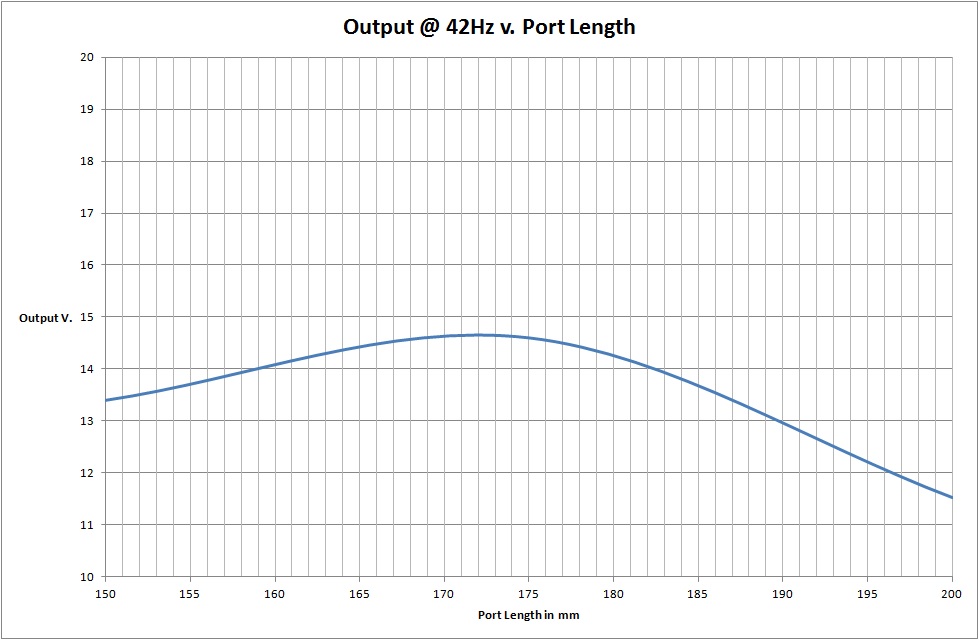
As you can see, the highest output occurs around 172mm, which is what I decided on. The winISD programme is very good, but it indicated that the -3dB point would only just make the 42Hz point, that is why I chose to tune it to that point.
DaveP

From the winISD programme, I got a rough idea of the ball park lengths, so I prepared 150mm, 175mm and 200mm tubes from 40mm OD plastic pipe.

I set up the mic to catch both the speaker and port outputs, then I measured the output from the mic-pre with the three different port lengths.

As you can see, the highest output occurs around 172mm, which is what I decided on. The winISD programme is very good, but it indicated that the -3dB point would only just make the 42Hz point, that is why I chose to tune it to that point.
DaveP
According to WinISD, what is the shape of the LF response? Is it under or overdamped, or critical?DaveP said:I have tested various port lengths to maximise the output at 42Hz (lowest note of a bass guitar)
The winISD programme is very good, but it indicated that the -3dB point would only just make the 42Hz point, that is why I chose to tune it to that point.
In particular, with underdamped alignment, optimizing for one specific LF note may be detrimental to the adjacent range.
In the attached pic, both have the same level at 42Hz, but they are very different in the low-mid.
Attachments
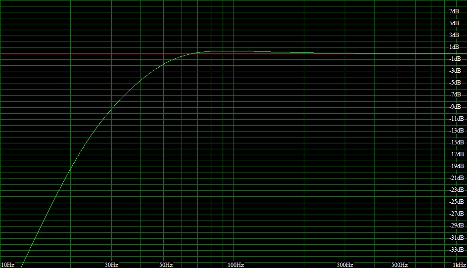
The response is the usual 0.707 alignment, so flat until the roll off, the -3dB is around 42Hz according to the program, I tuned the port to get the response the program predicted.According to WinISD, what is the shape of the LF response? Is it under or overdamped, or critical?
I appreciate your point, I wouldn't want a response that just peaked in the bass. This is the response predicted for a 24L cabinet tuned to 34.5Hz which requires 2x 172mm ports from winISD
This is the new Impedance curve, the meter won't read below 20Hz very well.
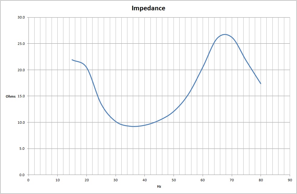
It was a single peak around 78 ohms in free-air.
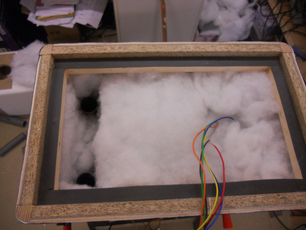
A thin foam strip makes it airtight.
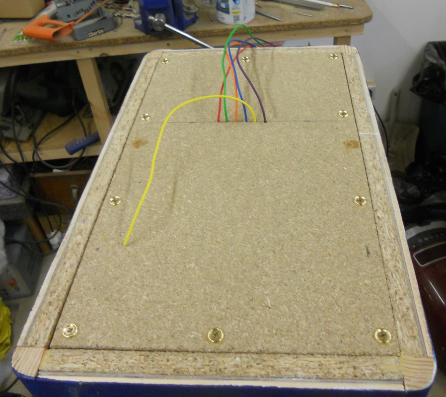
The crossover will be mounted on the back.
This one can now have its finishing coats and the felt panel fitted.
DaveP
The first one is almost finished with two coats of varnish and most of the crossover finished.

I cut out the wool felt midrange surround with a craft knife.

The tweeter looks a bit radical, but it works fine.

For a prototype, it was necessary to mount the crossover externally so that adjustments and testing could be done in a reasonable time.
There are zobel components on the bass and mid-range speakers but it was not really worth putting on the tweeter.

These are the Impedance figures, the main task was to get them as equal as possible across the crossover points of 500Hz and 5kHz.

All I have to do now is make a suitable Baffle Step coil and fix the input terminal on a bracket.
I have listened to a mono recording of Abbey Road as a test and it seems to be just about right, but it does need a baffle step coil around the 0.2 mH mark, but I shall do the calculations to make sure.
DaveP

I cut out the wool felt midrange surround with a craft knife.

The tweeter looks a bit radical, but it works fine.

For a prototype, it was necessary to mount the crossover externally so that adjustments and testing could be done in a reasonable time.
There are zobel components on the bass and mid-range speakers but it was not really worth putting on the tweeter.

These are the Impedance figures, the main task was to get them as equal as possible across the crossover points of 500Hz and 5kHz.

All I have to do now is make a suitable Baffle Step coil and fix the input terminal on a bracket.
I have listened to a mono recording of Abbey Road as a test and it seems to be just about right, but it does need a baffle step coil around the 0.2 mH mark, but I shall do the calculations to make sure.
DaveP
After some experimentation this crossover circuit sounds pretty good to me.

The tweeter has a 6dB pad because it is 6dB more efficient than the rest of the drivers.
The mid and bass both have Zobels to keep the crossover points stable.
The 0.2mH coil passes below 5kHz and the 2mH coil below 500Hz. The 5uF cap allows a path for the tweeter current to return to source. The 48uF does the same for the mid-range.
The baffle step for this speaker width (28cm) puts it very close to the mid/bass crossover point, so I have just bypassed the tweeter and mid with a 6.8 ohm resistor to obtain the same attenuation as a baffle step coil.
It seemed kind of pointless to go to the trouble of neutralising the natural inductance of the drivers with Zobels, only to add inductance with another coil.
The sound of the recordings I'm familiar with sound very full and correct with this crossover.
DaveP
john12ax7
Well-known member
I've enjoyed following this thread. What is the advantage of the seperate tweeter? See this a lot on B&W but not many others.
Do you mean in a three way system or having it out of the box?What is the advantage of the separate tweeter?
To answer both:
I would prefer to have just two drivers but an 8" breaks up really badly at the top end and a mid range that covers well for a low crossover point can't make the top end. Most tweeters can't do much at 1kHz.
I have put the tweeter out of the box to avoid the diffraction effects of the box edges. Ideally in a box, the tweeter should be placed asymmetrically off centre as it is very prone to diffraction where the ear is most sensitive. But I have found that off centre line placement does not sound right so that leaves an asymmetric shaped box which doesn't look so good and is harder to make, so I decided to take it out of the box altogether and make the distance to the edge so small that the wavelength concerned is out of the sensitive range. It does look weird though, I agree.
Before I took this radical step, I took measurements of the output with it in a conventional box with a condensor mic and the output varied enormously in the 2k to 4k region due to the sound going around the corners at different wavelengths.
DaveP
john12ax7
Well-known member
I meant having it out of the box.
I agree about 8" two way systems, don't sound quite right.
I agree about 8" two way systems, don't sound quite right.
These are the final mods and the project is now finished.

I gave in after lots of listening tests and fitted a 1mH coil, this cuts the top end just enough to balance the bass nicely. The bass loss due to the baffle size kicks in around 400~500Hz. All my favourite tracks sound right with this circuit.
This is how it physically looks. A prototype circuit needs lots of room to make changes as necessary. The baffle step coil was epoxy resin glued and strapped down with a plastic strip. Some gold plated terminals finish off the crossover.

I also lowered the tweeter as far as it would go and fitted a felt pad to absorb diffraction near the mid-range.

This is the finished monitor, it weighs 31.6 lbs, so it's no lightweight!

I can now finish the second speaker, but I won't bore you with that, this project is now over from my end.
Thanks for following.
DaveP

I gave in after lots of listening tests and fitted a 1mH coil, this cuts the top end just enough to balance the bass nicely. The bass loss due to the baffle size kicks in around 400~500Hz. All my favourite tracks sound right with this circuit.
This is how it physically looks. A prototype circuit needs lots of room to make changes as necessary. The baffle step coil was epoxy resin glued and strapped down with a plastic strip. Some gold plated terminals finish off the crossover.

I also lowered the tweeter as far as it would go and fitted a felt pad to absorb diffraction near the mid-range.

This is the finished monitor, it weighs 31.6 lbs, so it's no lightweight!

I can now finish the second speaker, but I won't bore you with that, this project is now over from my end.
Thanks for following.
DaveP
After finishing the second speaker and testing, I thought the thread needed an update.

I added a baffle step coil of 1mH, bypassed at 500hz with a 3.3 ohm resistor. This resistor is essential, without it the bass is great but the top end is muffled. The -3dB point corresponds to the baffle width wavelength of around 500Hz.
The result was amazing! I have tested them with a wide range of music including dance and the bass is outstanding.
Garbage's stupid girl felt like the kick drum was in the room, very very solid. All the mids come out through the mid drivers and the definition and stereo image is very good. With the crossover at 6kHz, only the highest fizz comes from the tweeter.

The baffle step coils are lower right in these pics of the backs. It is not difficult to wind your own air cored coils, the inductance builds quicker with narrow width but wider diameter (Tip). You do need a decent inductance meter though, testing with a 400Hz to 1kHz signal is the standard frequency I believe.

These were not cheap to make, if I had to make another pair, the drivers alone would cost around £400, it was just that I already had the bass and tweeter units already. The series crossover works really well, although the schematic does look complicated. The key to the results I got were down to the testing of each component and matching the zobel components to the drivers. This design was very labour intensive, so fine if you are retired, not so good if you are pressed for time. Getting the enclosure the right volume and making it solid and rigid, then tuning the twin reflex pipes, is well worth the effort.
DaveP

I added a baffle step coil of 1mH, bypassed at 500hz with a 3.3 ohm resistor. This resistor is essential, without it the bass is great but the top end is muffled. The -3dB point corresponds to the baffle width wavelength of around 500Hz.
The result was amazing! I have tested them with a wide range of music including dance and the bass is outstanding.
Garbage's stupid girl felt like the kick drum was in the room, very very solid. All the mids come out through the mid drivers and the definition and stereo image is very good. With the crossover at 6kHz, only the highest fizz comes from the tweeter.

The baffle step coils are lower right in these pics of the backs. It is not difficult to wind your own air cored coils, the inductance builds quicker with narrow width but wider diameter (Tip). You do need a decent inductance meter though, testing with a 400Hz to 1kHz signal is the standard frequency I believe.

These were not cheap to make, if I had to make another pair, the drivers alone would cost around £400, it was just that I already had the bass and tweeter units already. The series crossover works really well, although the schematic does look complicated. The key to the results I got were down to the testing of each component and matching the zobel components to the drivers. This design was very labour intensive, so fine if you are retired, not so good if you are pressed for time. Getting the enclosure the right volume and making it solid and rigid, then tuning the twin reflex pipes, is well worth the effort.
DaveP
5v333
Well-known member
Hats off!!
Next projekt:
Stereo tube power amp
Next projekt:
Stereo tube power amp
5v333
Well-known member
dear lord... 
Similar threads
- Replies
- 3
- Views
- 279
- Replies
- 26
- Views
- 6K


![Electronics Soldering Iron Kit, [Upgraded] Soldering Iron 110V 90W LCD Digital Portable Soldering Kit 180-480℃(356-896℉), Welding Tool with ON/OFF Switch, Auto-sleep, Thermostatic Design](https://m.media-amazon.com/images/I/41gRDnlyfJS._SL500_.jpg)


