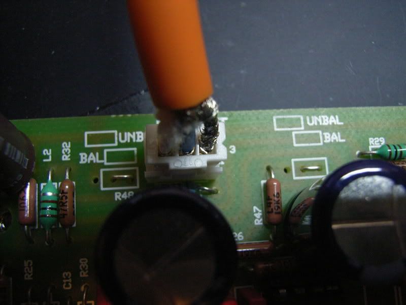
3D "AIR" EQ - "Night EQ" PCB's Complete!

GroupDIY Audio Forum

Help Support GroupDIY Audio Forum:

This site may earn a commission from merchant affiliate links, including eBay, Amazon, and others.
Thanks Harpo,

As always, you rock! You know I didn't even spot the AIR band was only ADDITIVE... pays to look doesn't it! Well I'll prob do just that swap out one of the remaining 2 pots I have for the 640hz and use the 79K1 for the 'AIR' band.

Thanks again!

Matt
 
Hi,

I just got one of the channel of my Night EQ completed and it doesn't work!

The voltage on the IC socket is okay (I use +/- 15V) but some how it only produce very weak sound in bypass mode and have no sound at all when the EQ is switched in. I would like to verify the signal path but I found that the schematic by kevin (Thanks for the hard work!) is only part of the circult on Peterc's PCB (Thanks for the pcb work too!).

Is there any full schematic of the PCB including the PSU parts and some bypass caps?

Thanks
laiben
 
[quote author="laiben"]Hi,

I just got one of the channel of my Night EQ completed and it doesn't work!

The voltage on the IC socket is okay (I use +/- 15V) but some how it only produce very weak sound in bypass mode and have no sound at all when the EQ is switched in. I would like to verify the signal path but I found that the schematic by kevin (Thanks for the hard work!) is only part of the circult on Peterc's PCB (Thanks for the pcb work too!).

Is there any full schematic of the PCB including the PSU parts and some bypass caps?

Thanks
laiben[/quote]

Post a link to some "Close up" pics & I'll take a look.

I've built a few of these with no problems.
The Schematic really isn't missing much at all.

Did you install the jumpers???
 
[quote author="khstudio"][quote author="laiben"]Hi,

I just got one of the channel of my Night EQ completed and it doesn't work!

The voltage on the IC socket is okay (I use +/- 15V) but some how it only produce very weak sound in bypass mode and have no sound at all when the EQ is switched in. I would like to verify the signal path but I found that the schematic by kevin (Thanks for the hard work!) is only part of the circult on Peterc's PCB (Thanks for the pcb work too!).

Is there any full schematic of the PCB including the PSU parts and some bypass caps?

Thanks
laiben[/quote]

Post a link to some "Close up" pics & I'll take a look.

I've built a few of these with no problems.
The Schematic really isn't missing much at all.

Did you install the jumpers???[/quote]

do you mean the balance/unbalance jumper? yes. I short the jumpers like this for balanced output:
RIMG2063.jpg


BTW I will wire the other channel to see if it works.. Thanks for looking Kevin!

laiben
 
A quick question:

Right below R26 is a jumper labeled "OR link." Is this used instead of R26 in some instance or do both of them have to be in place?

Cheers,
--
Don
 
[quote author="idylldon"]A quick question:

Right below R26 is a jumper labeled "OR link." Is this used instead of R26 in some instance or do both of them have to be in place?

Cheers,
--
Don[/quote]

As I understand if you do not short the "OR link" below R26 the bypass LED will not work.

BTW there are two R26s in the PCB, I am talking about the one next to the switch.
 
Thanks, guys! Yeah, I noticed the other direct links were also labeled 0R, which, as you suggest means a "zero ohm" jumper. I guess it was a bit of a "duh" moment for me!

Cheers,
--
Don
 
I'm trying to wire the bypass LED's to the boards and was curious how to do that. I see 4 holes but have only 2 legs on the LED. Can anyone clarify?

Thanks,
Adam
 
[quote author="bluezplaya"]I'm trying to wire the bypass LED's to the boards and was curious how to do that. I see 4 holes but have only 2 legs on the LED. Can anyone clarify?

Thanks,
Adam[/quote]

Check the trace on the PCB. You can just install one LED and leave the other two holes open. I have no idea why it design like this, maybe the designer think some builder want two bypass LEDs? BTW check the voltage of the bypass LED, don't burn it.
 
EDIT: Ah, a boneheaded move on my part. I had missed the correct value for R48 by one decimal point! I'll leave this posted as it might help someone as absentminded as I've been lately. I lost my mother a couple of months ago and just haven't been tracking too straight since then. It's a hard weekend as it would've been her birthday as well as Mother's Day.

Well, I finished up my build and am having a small problem, which is most likely something I've connected wrong. Here it is:

When the EQ is engaged the bypass LEDs are lit, but the EQ works and sounds excellent. (EDIT: On further inspection, it appears the LEDs are supposed to be lit when the EQ is engaged and dark when bypassed--correct?)

When I move the bypass switches to "bypass" mode, the gain goes through the roof and I get a completely distorted sound. I've tried reversing the wires going to the outside poles of the DPDT toggle switch, but it's still the same problem

I have the same problem on both boards and I'm using it unbalanced (links in place) wired into my Neotek's patch bay, which runs at +4 unbalanced.

Here's a pic:

NightEQinside.jpg


Any ideas?

Cheers,
--
Don
 
Just wanted to give Kevin and Peter kudos for such a great project. Now that it's done and hooked up to my console, I can see that it will get a lot of use. I've been looking for a good EQ for mixdowns for quite a while, but have been hindered by the high price tags. This project fit the bill perfectly and I saved a ton of money.

Also, thanks to Harpo for the spreadsheet. It was a piece o' cake to plug in the numbers and adjust the resistors for each pot. When everything is centered and I switch between in/out, there is no audible difference at all.

Cheers,
--
Don
 
I installed a w005 brige rectifier in my green psu. Im sure it will be fine but I hav noticed that most of the posted pics of finished units seem to use a much beefier Bridge rectifier. Right above idylidons pic looks like a much larger BR. I have a 500 volt BR but that sounds like overkill. Would there be a reason not to use the larger, Shoud I stick with the w005, which I believe is a 50 volt BR?
 
I quess what Im asking is first, are there additional benefits to using a larger bridge rectifier, for example heat dissapation? Im assuming a 500 volt bridge rectifier handles UP TO 500 volts and rectifies lower voltages as well.
 
[quote author="W DeMarco"]I quess what Im asking is first, are there additional benefits to using a larger bridge rectifier, for example heat dissapation? Im assuming a 500 volt bridge rectifier handles UP TO 500 volts and rectifies lower voltages as well.[/quote]

I'm sorry I can't give you a "Definite" answer but a higher rated rectifier shouldn't be a problem. I use 1n1003 - 1007's on my PSU's all the time & the voltages are low... 12v - 60v max. I'm pretty sure these are 200 - 1000v rated parts.

:::EDITED::: :oops:
 
[quote author="W DeMarco"]I installed a w005 brige rectifier in my green psu. Im sure it will be fine but I hav noticed that most of the posted pics of finished units seem to use a much beefier Bridge rectifier. Right above idylidons pic looks like a much larger BR. I have a 500 volt BR but that sounds like overkill. Would there be a reason not to use the larger, Shoud I stick with the w005, which I believe is a 50 volt BR?[/quote]
Depending on your transformer it might work (didn't look up the datasheet, so assuming yours is 50V/C?). With a 2x15VAC or center tapped 30VAC secondary and for safety 10% line overvoltage this BR will see ~47V (30V * 1,1 overvoltage * 1,414 for peak). Close, but maybe or better hardly enough. The safety margin for 20-50% line transients is still missing. Your transformer secondary may be lower. A 2x18VAC transformer will sure be too much.
Another part is the surge current when powering up. Have a look at OnSemi's Linear & Switching Voltage Regulator Handbook.
I'd probably use a BR with more beef (or 4x 1N400x). YMMV
 
I'm trying to sort out resistor values to use 12 position rotary switches to make a 'mastering version' Night EQ.

It's my intention to make 1db steps from -5 to +6. If these 1dB steps seem too steep in use, I have a second set of boards to do 1/2 dB steps :wink:

I've used the spreadsheet that Harpo kindly supplied to work out the R total, R centre and R series values that I need, but I'm really out of my depth in determining the formula that will calculate the resistor values for my 1dB steps.

Can anyone chime in here and give me a hand? Am I even heading in the right direction with what I've got so far?

Here's what I've worked out using the spreadsheet:

table1.jpg


thanks :thumb:

Rob
 
[quote author="Harpo"]Hi Rob,

something like this excel sheet :wink:

regards
-Harpo[/quote]

Hi Harpo,

That's fantastic thanks! Was this already available or did you put it together last night?

Either way, many thanks. :sam: for that man :grin:
 
Back
Top