3D "AIR" EQ - "Night EQ" PCB's Complete!

GroupDIY Audio Forum

Help Support GroupDIY Audio Forum:

This site may earn a commission from merchant affiliate links, including eBay, Amazon, and others.
Hi fellow builders and diyer's!

I'm building a stereo unit here and I have a peculiar problem:

One channel is working as expected and sounds very good and is dead silent.

The second channel works all the way up to "air" frequencies:  I can hear only a very slight boost in selected air frequencies, even if I boost the air gain full on. With the working channel the air boos works as expected. When I flip the rotary switch through the air frequencies, I can hear them changing correctly, but the boost is just way too low.

I built the channels identical, measuring all the resistors and now I wen't through the resistors once more and all seem correct (*knocking on wood*). I also checked wiring many times but can't find anything. Also tried replacing the 500K pot for air gain, but the effect (or lack of it) still remains.

Anyone has a clue what could be the culprit/ problem here?

Thanks a lot in advance!
 
Whoops said:
Hi,
I would like to do a version of the night EQ where instead of having separate controls for the channels, I would only have one control for each band, controlling both left and right channels at the same time.

I was thinking about Dual Gang 470K Rev Log Pots, audiomaintenance has them.
http://www.audiomaintenance.com/acatalog/om-01-055_extended_info.html

Even if the "Air" control and "Vari" switchhad to be independent, it would be great to have only one control for the "Sub" , "40hz", "100hz", "650hz" and "2,5K"

Do you think it's possible ?

didn't find any answer to this post, so i am asking again ;-)

did anyone manage to control two boards with one set of dual gang potentiometers? i want to have matched channels and save some space on my front panel :)
would these pots work? http://www.audiomaintenance.com/acatalog/om-01-055_extended_info.html

do i have to install separate controls for each channel for the air band, air gain and bypass control?

thanks
weiss
 
Hey Weiss,

I haven't finished my unit yet (it's been sitting on the bench/shelf for quite a while now). Yet I remember someone suggesting 50K pots instead of 500K ones (requires recalculating and swapping some resistors on the board), cos 50K pots are more readily available/cheaper.

Matching pots is critical for this unit to get flat response in mid position. Theoretically what you aim for is possible, but requires tedious pot matching (10-20% deviance between gangs). Two ideas to counter mismatches that should make life much easier:

(1) use stepped controls (either dual mono [2U] or stereo [1U]) -- elegant solution
(2) stay dual mono with well-matched pots and process material in MS mode -- more versatile solution

I have made up my mind a long time ago. When I go back to the unit it will be option 2.

 
Script said:
I haven't finished my unit yet (it's been sitting on the bench/shelf for quite a while now). Yet I remember someone suggesting 50K pots instead of 500K ones (requires recalculating and swapping some resistors on the board), cos 50K pots are more readily available/cheaper.

Matching pots is critical for this unit to get flat response in mid position. Theoretically what you aim for is possible, but requires tedious pot matching (10-20% deviance between gangs). Two ideas to counter mismatches that should make life much easier:

(1) use stepped controls (either dual mono [2U] or stereo [1U]) -- elegant solution
(2) stay dual mono with well-matched pots and process material in MS mode -- more versatile solution

I have made up my mind a long time ago. When I go back to the unit it will be option 2.
Thanks for your reply! I ask because i already have the potentiometers here and don't want to buy new ones. So controlling both pcb's with a single set of pots would work?
 
I see. Then why not go for it. Should be easy enough to wire everything (even if wiring "sucks" ;)

Either way, I'd also measure the dual gang pots. Do the two gangs give you roughly the same resistance readings?
(1) Measure between pins 1 and 3. If values of both gangs are identical/close = good.
(2) Measure between pins 1 and 2 (with wiper/pot set to mid position). If values are identical/close = good.

If values are not close at all, hmm... wire it all up anyway and listen.

There is a mathematically ideal resistance reading at mid-position (btw. pins 1 and 2) of 1/10th of total pot resistance. With a dual-gang pot this is highly critical cos any deviation between gangs will result in volume differences between L and R channels.

Found an excel "calculator" file on my harddrive (originally by Harpo -- hope it's okay to post) that might be useful, though untested by me. Download and delete the ".pdf" to open it as an excel file.

Viel Glueck
 

Attachments

  • 3D-EQ_PotTweaking.xls.pdf
    20.5 KB
Read back in the thread. Now I know why the boards have been in a box on a shelf for such a long time. This unit needs meticulous resistor calculation (not just pot series resistor for mid-centering the pots; first it needs tweaking the frequency resistors, and then the gain) to get a flat response when engaged with pots set to zero.

@Harpo (and everybody else)
After getting the frequencies right, would getting the gain right not be better done by tweaking the 1K opamp input resistors (R10, 13, 16, 19, 22) rather than tweaking the pot series trimmers (orig. "5K62" per schematic)?
 
Script said:
Read back in the thread. Now I know why the boards have been in a box on a shelf for such a long time. This unit needs meticulous resistor calculation (not just pot series resistor for mid-centering the pots; first it needs tweaking the frequency resistors, and then the gain) to get a flat response when engaged with pots set to zero.

@Harpo (and everybody else)
After getting the frequencies right, would getting the gain right not be better done by tweaking the 1K opamp input resistors (R10, 13, 16, 19, 22) rather than tweaking the pot series trimmers (orig. "5K62" per schematic)?

i don't get this. why is the unit not working properly when using the right values for the resistors?
 
i don't get this. why is the unit not working properly when using the right values for the resistors?

Read all posts by Harpo in this thread about getting the frequencies right.
Shouldn't stop you from soldering in the 500K's.
 
Thanks man. I will do ;) So i use the dual gang pots, but what about the frequency selection of the air band. is it possible to use one switch for L and R?
 
Script said:
After getting the frequencies right, would getting the gain right not be better done by tweaking the 1K opamp input resistors (R10, 13, 16, 19, 22) rather than tweaking the pot series trimmers (orig. "5K62" per schematic)?
No. Tweaking/increasing the resistor in front of the non-inverting gain stages wouldn't change a thing (except increased resistive noise). You'd still need to adjust the series resistors at the rheostats because of the -for usual- +/-20% pot tolerances.
For a single knob per frequency band stereo build you'd need a lot of rev.log pots (read hundreds, with a little luck every 20th pot might be just close enough to be acceptable) for a resistance at center, total resistance and taper matching.
 
Let's see whether I got this right.

The cap values are also critical to get the HP and LP filter stage right (and with it the filter stage gain). Because with less-than-ideal filter cap values (and resistor values), these inconspicuous pot series resistors suddenly fulfill a triple function: (1) to set the gain for the summing opamp, (2) to set the pot's centre position, and (3) to compensate for messed-up filter stage gain. This makes any compromise here more or less messy, even impossible -- at least on paper. Right?

Why? Because less-than-ideal cap values mess up the filter bands. This could be adjusted by altering the filter resistors. However, doing that messes up the opamp gain. The then less-than-ideal opamp gain could be compensated for by adjusting the pot series resistor. However, this messes not only with the centre position of the pot (which takes some effort to set right by adjusting this very same pot series resistor), it also messes with the band's gain into the summing opamp determined also by this very same pot series resistor. Good luck with that!

Said differently, in order to not mess things up down the chain, the real-world filter cap values need to be trimmed to be as spot-on as possible in the first place. Solving less-than-ideal capacitance of, for example, 0.9uf+1.0uf=1.9uf requires adding 0.1uf in parallel (on the underside of the board) to get the required 2.0uf. Only then can we insert the exact(!) resistor values required for the HP/LP filter bands without messing up the filter stage gains. Once we get all this right we still have to compromise in the 'pot section' (weakest link in the chain) by either dropping the pot's zero position or accepting sacrifices in single band gain.


IDEAS
(1) Put trimmer in front of pot to make total resistance of pot 'look' like 500K or allow for pot-related adjustments? Eh? Not sure whether this adds to solving the 'how to set the "zero" position' problem at all without messing up gain again.
(2) Ideally there should be an extra gain stage in each band after the pots(?) exclusively for trimming gain offsets of up to 1db or so, but there isn't. Maybe in the next revision.
(3) I don't like the idea of adding 14 or more trimmers to a unit. I'd rather tag resistors in parallel.
(4) Here's what I'd do: Get the filter bands spot-on first and then insert the calculated pot series resistor. Then dial in 'zero' on non-indented pot on the front plate until frequency response is flat and put a knob on it with its 'visual' marker pointing to 12 o'clock.
(5) In use, take the pots and all other flat-frequency issues (like pot bending law and max volume attenuation) out of the L/R matching equation by running stereo material through two units in MS mode only. Then dial in desired sound without even looking at the face plate and A/B via hard bypass.

Hm, I still feel that there's something missing in my thinking (especially in Idea 1). Not sure though what.
 
Last edited:
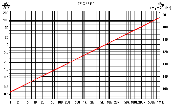
50k will give you way less noise, 500k is noisy
R-Noise-20kHz_700.GIF

so 10dB less noise
 
look for earlier posts of mine, I don't remember what I did, but it was very simple and it does have an audible effect when pushing signals
 
e.oelberg said:
Resistive/Johnson noise of the 500K resistor is -97.8dB. (@weiss: only by use of this single resistor value and per resistor. This -97.8dB is not the noise figure of the complete circuit...)
A 50K introduces -107.8dB, a 10K introduces -114.8dB of resistive noise.
Johnson noise in dB = LOG(SQRT(4* 1.38E-23 * 300 * 500,000 * 19,980))*20
with Boltzmann constant 1.38E-23 Joules/Kelvin, assumed room/box temperature 300 Kelvin, 500,000 your tested resistor value in ohm and bandwidth 19,980Hz for your 20Hz...20kHz audible range of interest.
With highest gain setting, this 500K variable resistor/pot/rheostat is dialed in for zero ohm (=lowest resistive noise), further leading to the conclusion that the parts value of the series resistor in front and corresponding feedback resistor as well might be responsible for these unnessesary high numbers ...
 
fazeka said:
With Peter making PCBs again, anyone going to have front panels?

You should talK with Dan, a lot of people bought this PCB's so I guess there would be some interest in cases or front panels.
If theres enough interest he might do a run:

http://groupdiy.com/index.php?topic=35422.0


Latest posts

Back
Top