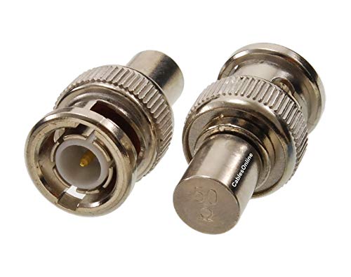
50 Ohm BNC termination

GroupDIY Audio Forum

Help Support GroupDIY Audio Forum:

This site may earn a commission from merchant affiliate links, including eBay, Amazon, and others.

warpie

Well-known member
Joined
Feb 7, 2009
Messages
1,603
I've been watching some videos where 50 Ohm BNC terminators are used and I noticed that there are two different types. One is connected in parallel to the probe (with a T style BNC) and another that is connected in series to the probe.

What is the difference and when each type should be used?
 
Normally the terminator goes on the T , if it was in series wouldnt it be an attenuator ?
 
it says in the FAB (features, advantages, and benefits) that its for use with oscilloscopes.

If looking at a 50 ohm signal source that needs 50 ohm termination using a scope. Oscilloscope input impedance is generally megohms.

JR
 
I see now , the terminator you point out removes the need for the T junction .
 
So both versions are connected in parallel but the one with the male-female connection (bottom pic) omits the need for a T-junction?

41Hbgx4wzPL.jpg

24C8482-40.jpg
 
Thats seems to be it alright ,

Look at the price difference though , the T junction and usual endstop type terminator probably dont cost 5 euros , the Tek DC-GHZ feedthrough is more like 180
 
Last edited:
Thats seems to be it alright ,

Look at the price difference though , the T junction and usual endstop type terminator probably dont cost 5 euros , the Tek DC-GHZ feedthrough attenuator is more like 180
Yes, I'm aware of the price difference and I'm not planning to spend $180 for a terminator. The photo is just an example.

OK then, no difference. That makes sense. Thanks for your help.
 
My guess is when your dealing with frequencies in the GHZ band even something like the t junction could be problematic or load the signal unessesarily with extra capacitance .
 
I remember working on RF cabling back in the day and it was all about matching loads and reducing VSWR. It turns out the std. BNC is pretty lousy in that regard, hence the other types, TNC, sma, N-type, etc. I was/am no expert, but remember a few things.
 
In a nutshell, the 50 ohms effectively lowers the cable capacitance compared to having it hi-z. With RF, you always match to get MPT, or maximum power transfer, which lowers what musipol said...

Plus when you get into the GHz areas, you start seeing the migration of electrons to the outside edge (skin effect) but never say that word with audio or you will receive 1000 lashes.
 
Plus when you get into the GHz areas, you start seeing the migration of electrons to the outside edge (skin effect) but never say that word with audio or you will receive 1000 lashes.
or mention litz wire... ;)

Skin effect is not well understood and occurs in as low as mains frequency power distribution cables. If you inspect high power transmission wires you will find a steel core for strength, surrounded by aluminum for it's lower resistance to reduce IxR losses. With the current mostly flowing in the low resistance outer aluminum wrap the steel core's resistance is not a concern. Run don't walk away from speaker wires based on this strategy. :cool:

Proper impedance for hi frequency interfaces is mainly to reduce reflections from mismatched terminations. I guess in theory this reflected energy degrades maximum power transfer, but the larger concern is from superposition interference from reflected waveforms beating with the original source signals.

JR
 
My understanding is that for audio frequencies there's no need for a terminator. But when is termination needed? At 1MHz? at 2MHz? at 3?

The reason I asked is because I'm about to calibrate a 2MHz old function generator and it requires 50 Ohms termination for most adjustments.
 
Last edited:
I can only say with certainty that characteristic impedance is no longer used for typical audio interfaces. Looking into the wayback machine such terminations were used for very long telephone audio cables (like undersea).

Modern audio interfaces are "bridging" so the input impedance is nominally 10x the source impedance. The most obvious example of this is mic preamps using 2k input terminations to be bridging wrt mic's 200 ohm source impedance.

JR
 
Thank you all. I'm aware of the matched/ bridged impedance concept.

My initial question had to do with the two different types of terminators that puzzled me but this was answered.

Then, I started wondering above what frequencies a terminator is needed.

That's all :)
 
Back
Top