670 signal amp/control amp woes

GroupDIY Audio Forum

Help Support GroupDIY Audio Forum:

This site may earn a commission from merchant affiliate links, including eBay, Amazon, and others.
You are not going to be able to do 10W with a 3.9k load because that would be 197Vrms.  So you will have to reduce the load resistor to something convenient that will stand 10W through it.

Remember that the reading on your scope will have to be divided by 2,828 to get to Vrms.

For example, 8 divisions at 1V /div =8Vp-p.

8/2.828 =2.83Vrms

best
DaveP
 
Hi Davep,

is their any chance you could send me the  Excel  graph thingy, been pull my hair out trying to set  it up on a MacBook.


cheers

skal
 
Waiting on a hammond , power tx for the project , then i have figure out , how  to get 440vdc for 12hb7 and about 250 to 420 for the finals.

regards

skal
 
Den,

I have emailed you an Excel chart for you to insert your own data.

You can copy the resulting chart into a pdf for posting

best
DaveP
 
:( gone and bought the wrong power tx,  i think got 374bx  375ct375 , putting over 800 vac rms

can i use a conventional and bridge full-wave rectifier or a full wave bridge rectifier, which one is the more reliable.

this thing, is going to put out  about 566vac peak and over a 1000 volt pk-pk  rms :eek: , i think i will stop here and wait , for a somebody with a bit more now how and the matter of power supply..

cheers

skal
 
Your Hammond 374BX is probably OK and 750Vac should give you about 530Vdc with solid state diodes and a CT.  (750x0.707=530V).

If you use a tube rectifier then you will have a much bigger diode drop across the tube.  You need to check the spec sheets for the rectifier and work out if you need any extra resistance in the diode leads too.

Do not use a bridge connection on this TX as it will give you over a 1000VDC which is dangerous when you are not sure what you are doing.

Its best to read a tutorial like Morgan Jones on rectifiers before you go much further.  Your capacitors will probably need putting in series as well, to handle the voltage, so check that out too.

Best
DaveP
 
Ok, using the 240vac tap on the primary ,and  using this diode rec  http://electriciantraining.tpub.com/14179/img/14179_182_2.jpg

getting 714vdc

:D

skal
 
Ok, using the 240vac tap on the primary ,and  using this diode rec

http://www.electronics-tutorials.ws/diode/diode18.gif?81223b and a 400ac motor cap

output from cap 560 ish

:D

skal
 
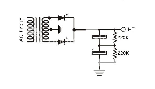
For voltages over 450V you need an arrangement like this for the capacitors sake, and be very careful


High voltages take no prisoners! :eek:
DaveP
 
Ok this what i have come up with for the smoothing stage...


feel free to comment
 

Attachments

  • VT670PSU2.png
    VT670PSU2.png
    150.7 KB · Views: 35
That looks OK, the actual capacitance will be 110uF as the caps are in series, but this should be fine.

The original Fairchild had just 4uF as the first cap, then a choke, followed by your arrangement but with two 140uF caps in series.

DaveP
 
Ok at the moment i am try to figure out  how to drop some of the secondary  voltage, to get me to 440vdc.

My thinking  is 556 vdc-440 vdc =116    So R=V/I =828.5 is this correct?

cheers

skal
 
Ok at the moment i am try to figure out  how to drop some of the secondary  voltage, to get me to 440vdc.

My thinking  is 556 vdc-440 vdc =116    So R=V/I =828.5 is this correct?

Yes that is correct for 140mA current.

0.14x116=16.24W which is a hell of a 820 ohm resistor.  But it may not be as bad as that depending on the regulation of your transformer.  You may find that under load it is no longer 556V but something lower.  It's best to not fix anything in stone until you have constructed the regulated supply as well, because the voltage drop of your passing tube may well be different too.  The main idea is to get the correct regulated voltage and current, just set the voltage drops to achieve that.

You will need to use a 25W or 50W metal clad resistor screwed to the chassis or a heat sink.

best
DaveP
 
oh ,

that's  cool, i  already got an ss regulator for the  signal amp and 12ax7  that can take 450vdc plus , so that's cool.

so just load the transformer with the ss regulator and finals  and take it from their .

cheer

skal
 
Ok , after along break from the diy i'am back to the control amp  again, at the moment  i am beating my head against a wall .

i was looking at Davep's  control amp gain structure  and i am a bit confessed . could someone in lighten me


http://i42.tinypic.com/25q9lio.jpg

about whats going on in the chart

cheers

Skal

 
so here is some side porn  just 1 channel at the moment, still trying to iron out the power supply to much ripple going to 12bh7.. ;D
 

Attachments

  • Photo on 27-10-2015 at 14.27.jpg
    Photo on 27-10-2015 at 14.27.jpg
    243.1 KB · Views: 54
well ,  i  have learn't  a bit so  far building this DC amp , how current,s interact with voltages  and so on and so on , the thing i can take away form this stage of the project , is  that you should never give up  and you should keep on going to you can understand whats going and how things change your decision making.


Anyway cheers to Alexc & Davep  for giving me the inspiration to carry on this project, still need to figure out how to power this baby but that another piece in the puzzle.... 8)

Skal
 
Back
Top