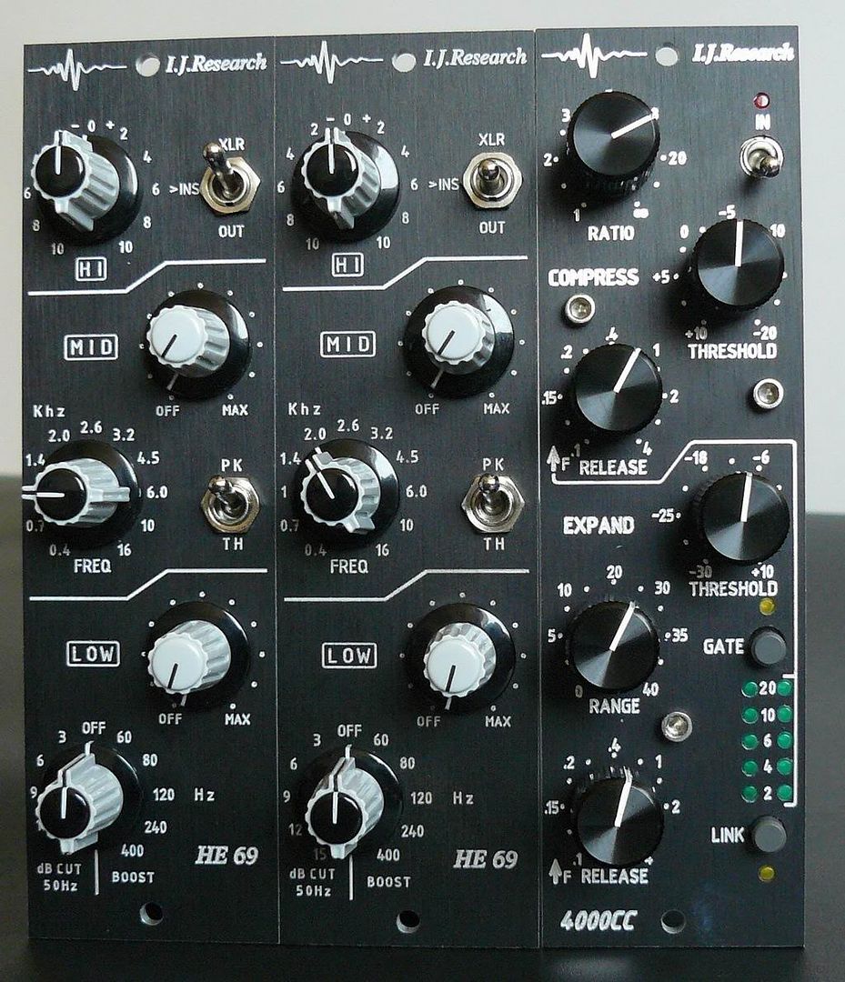
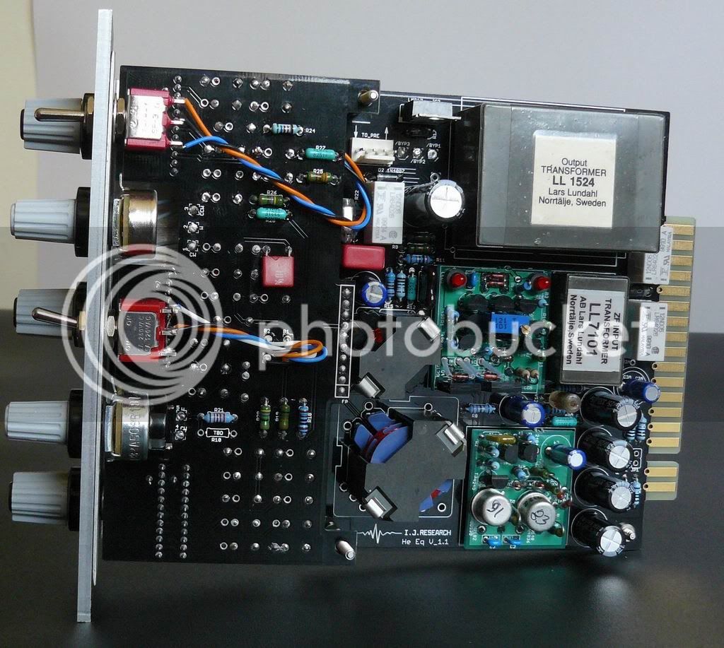
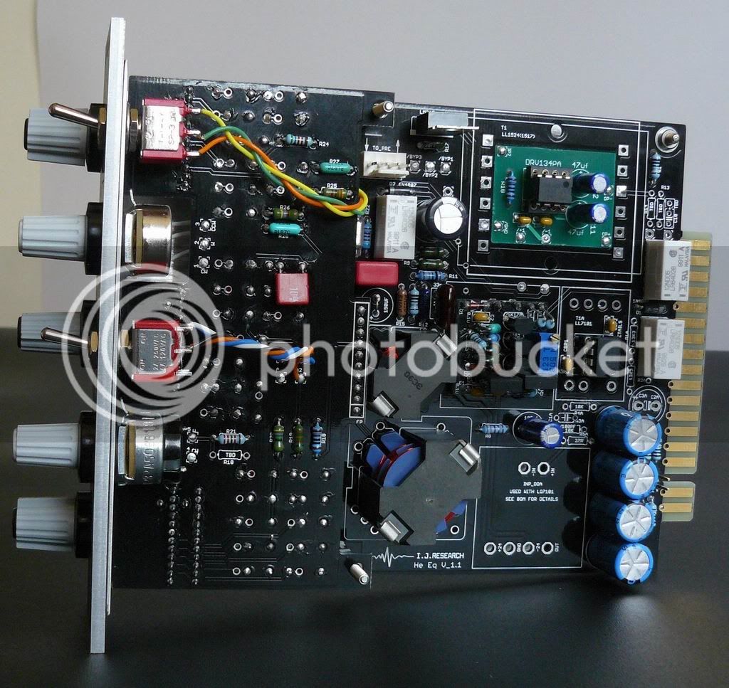
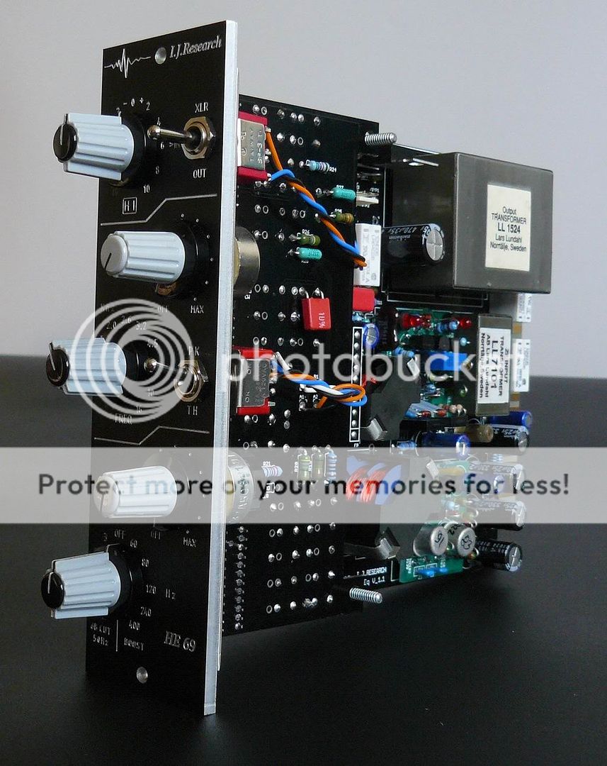
Hi guys, and sorry it took so much time - currently, I working in Tel Aviv and living in Haifa,
it is about 100 km to each direction back and fourth every day, and absolutely had no time for anything.
Finally, I had some time, and, as first priority thing, putting here the fix.
I tried to source low profile 2x11pos switch, but is is impossible, or I missing something.
The fix is a bit barbarian, but I checked it and it works 100%.
Sorry for bad quality of pictures, I had to build/test both pcb versions of this EQ from scratch in limited time,
as first proto is working at my friend's studio in St. Petersburg (he using it without low cuts and happy).
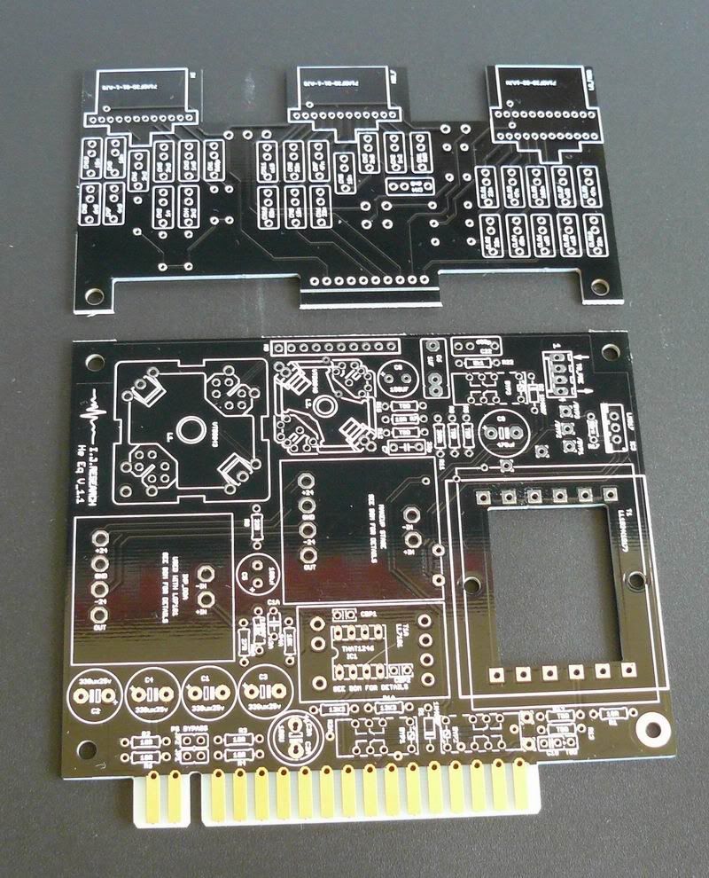
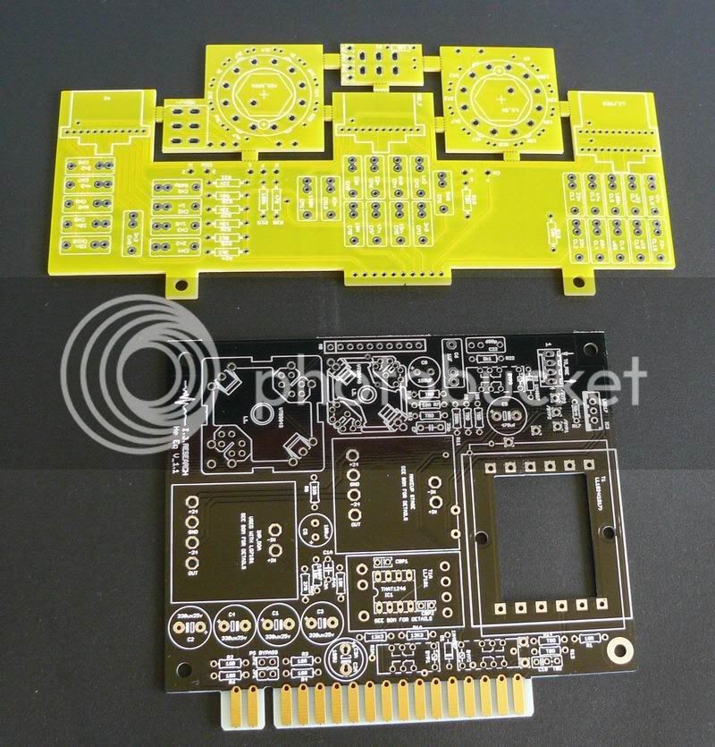
There were 2 versions of PCB's. One version needs only the low frequency switch fix.
It goes exactly as
hobiesound said:
well guys the fix seems easy enough doesn't it.... for the low cut AND the low boost to function properly you NEED a dual gang 1x11 switch and a trace cut between a6 and A because that trace permanently bypasses the low cut. And then wire both decks of the switch like on the original schematic. Also you'll need to wire all switches and pots on the filter pcb offboard to facilitate for the bigger low boost/cut switch.
disclaimer: i don't own this pcb so this advice is just coming from me looking at the schematic and comparing it to the original schematic. I do however have a working pcb layout of this filter circuit.
greetings,
Thomas
Many thanx to Thomas for good explanation, and here are the pictures:
- Schematic of how-to wire the switch:
http://i251.photobucket.com/albums/gg291/diy33609/HELIOS_FIX/SWITCH.jpg
- Da FIX:
http://i251.photobucket.com/albums/gg291/diy33609/HELIOS_FIX/1.png
- Semi-hi-res pic showing all this:
http://i251.photobucket.com/albums/gg291/diy33609/HELIOS_FIX/P1060256.jpg
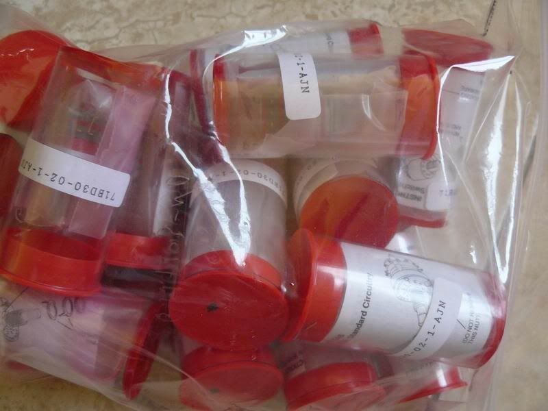
The switch which fits is Grayhill, 71 series, 71BD30-02-1 AJN.
PLEASE CHECK WITH DATASHEET,
www.grayhill.com/catalog/Rotary_71.pdf
because I used Grayhills pulled from old measurement equipment,
and they had no markings.
Fixing:
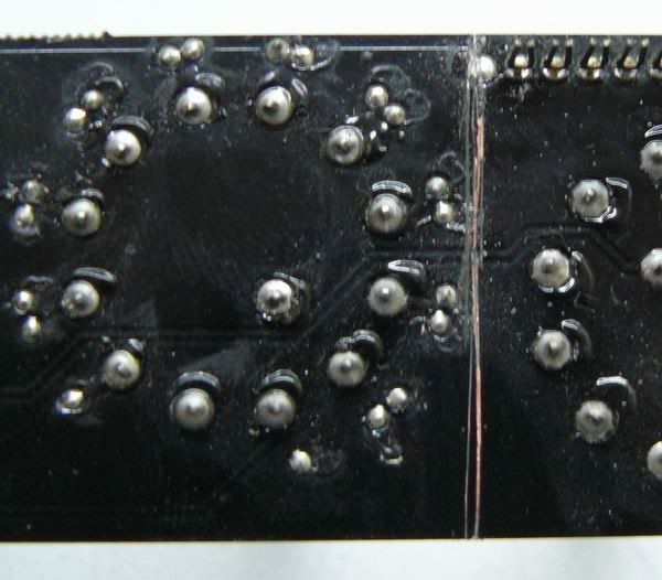
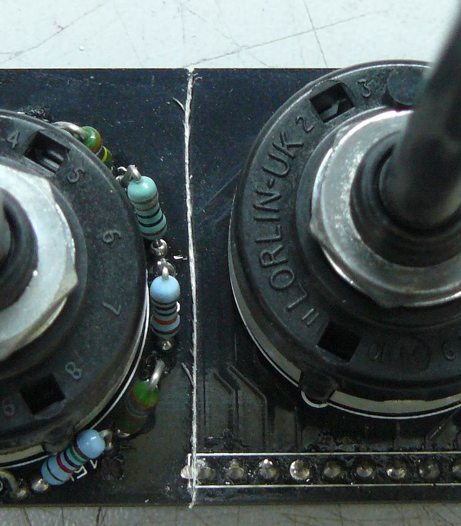
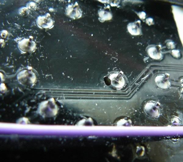
First, cut the PCB as shown here:
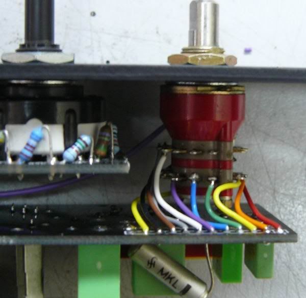
Wire the switch and connect both wipers to A! point.
This is the fix for low cuts issue.
As well, there were some PCB's with LOW BOOST problem.
If you have a problem with LOW BOOST switch (if it starts from +15db), the fix is simple as well.
Check this:
http://i251.photobucket.com/albums/gg291/diy33609/HELIOS_FIX/2.png
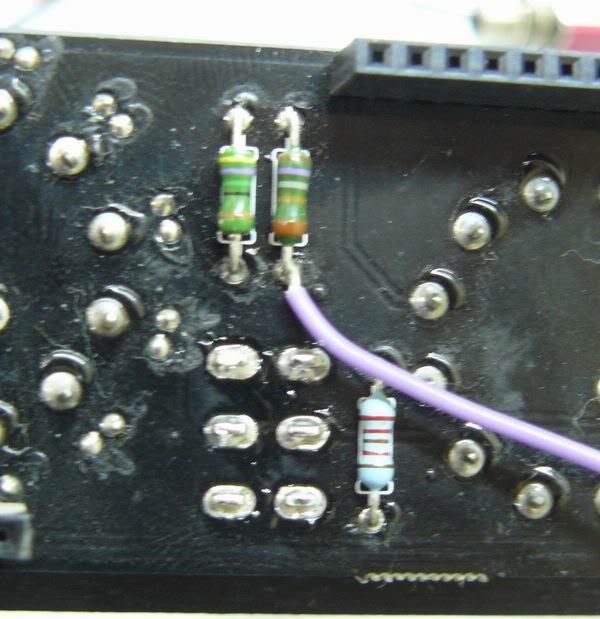
Cut 2 traces; for the trace on top layer, if low boost switch is not soldered, it is easy,
OR, if switch is already soldered on PCB,
drill the hole 1.5mm like here:
And connect wire as shown:
http://i251.photobucket.com/albums/gg291/diy33609/HELIOS_FIX/2.png
That's all. Here are all pros and cons:
http://s251.photobucket.com/albums/gg291/diy33609/HELIOS_FIX/


