6SN7 / 6CG7 preamp

GroupDIY Audio Forum

Help Support GroupDIY Audio Forum:

This site may earn a commission from merchant affiliate links, including eBay, Amazon, and others.
[quote author="rafafredd"]Mine is finally alive:

I know it looks funky, like all my latest DIY, but it sounds great, so... Who cares? [/quote]

Nice work Raf. I say neatness-shmeetness. I would always rather find a point-to-point mess than a surface-mount puzzle. :thumb:

Looking at your pics made me wonder again, does anybody make shields for octal tubes, like the ones we use on the 9-pin miniatures?
 
Circuitmaker, LTSpice, Orcad, etc.... All the flavas of SPICE are built on the same core, the difference is in the user interface. The simulation is only as good as the models, and all models are an approximation compared to the real thing. I've tried all three of those programs and they all lie when you ask them the right (or is it "wrong?") questions.

They are damned handy for drafting schematics, though.

For some, SPICE is a serious design tool. For me, it remains a toy for diddling around during lunch breaks. I use paper, pencils and calculator and yes, sometimes SPICE--but I fire up the soldering iron and test gear when I get serious about checking out and optimizing a design. Observed results from actual circuits are the only data I really believe.

Arguing about it is about as useful as saying that the wire stripper you use must somehow be better than mine. Tools are tools. Use what works for you.
 
[quote author="NewYorkDave"]Arguing about it is about as useful as saying that the wire stripper you use must somehow be better than mine. Tools are tools. Use what works for you.[/quote]

Yeah, you're right, bro. No use arguing about it.
icon_confused.gif


analag
 
no doubtbeing able to quantify aspects of adesign seems to justify the design...

do you have strippers from RS components in england? they are really the best tools I have ever used. and the silicone and neoprene sleeve insulators they carry are often much better than heatshrink
 
So, this thread is up again...

I just wanna say that pre sounds realy good, and I[m using low quality components, like old german mic input transformer that came out of an old dynaic mic with a thin mumetal shield, and a very cheap DI 20k:600 output transformer, that´s not what I would call low resistance windings. The 600 side has a DC resistance of aprox 140R, and I don´t seem to have headroom problems. ote that when I want more gain I use the transformerless output. I´ve put a switch on the front panel lebeled OUTPUT: transformer - transformerless. It´s very good on snare!
 
[quote author="NewYorkDave"]Oliver Read published his line amp circuit in 1952, and it uses a grid-leak biased AY7 in a shunt-fed output arrangement. I have no idea of its performance.[/quote]

After reading and re-reading PRR's analysis of this circuit, I've decided to try it. I have all of the parts in my junk drawer, except for the choke in the power supply. Can I get away with replacing that with a big resistor? What would the DCR of a choke that size be?

For instance, the UTC A-32 has 15Hys 30ma, 500 ohms. The S-27 has 30Hy 75ma, 350 ohms. Should I just go with a 1k 1W and see where that gets me?

Thanks!
 
Is there an updated schematic for this project? I saw this project a year ago and am just now getting around to building it. The original schematic is a broken link and I thought I had seen an updated one anyway, so... anyone have it and can post it to the thread?
 
Rafa, what transformers ARE you using? A few questions about your schematic if you don't mind as well.

1. What's with the 150k resistors in front of the input transformer? I haven't seen that on any of these designs. Forgive my ignorance, but what are they for?

2. How did you settle on the 20k:600 output transformer? I thought a I had seen a 2K4 output tranny being used, what was wrong with that? Couldn't the output be transformerless like NYDave's old schematic?

3. How much gain are you getting out of this circuit and what sources are you using it on?
 
My circuit was transformerless? I don't think so.

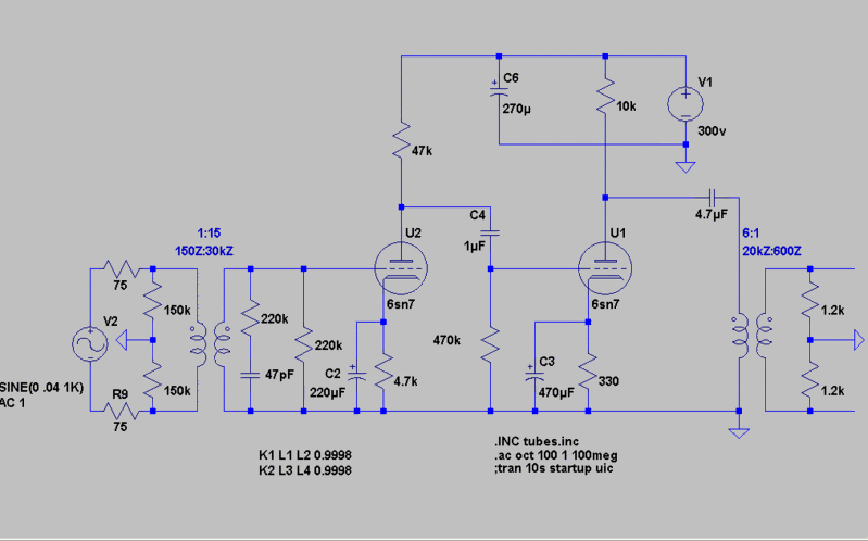
EDIT: I found the schem in my files and re-uploaded it:

ForRafa1.jpg


As I said in the original message, there is an output transformer, it's just represented on the schematic as simple voltage divider (R11, R12) for purposes of simulation in Circuitmaker. The input transformer is represented in very simplified form by the 50K source resistance, R1. Circuitmaker's transformer models never worked right for me.

Although originally I showed a 10K:600 output, 15K would be a better match to the 6SN7's plate resistance in this circuit.

Aha, now its all clear. I always wondered about that schematic with the resistors in weird places, I guess I should have read the description more carefully. So, ok, now the whole thing makes sense. I have a perfect chassis and input transformers that will go into this project. I'll just have to get some Edcor output tranny's and I'll be all set. Thanks for clearing it all up.
 
[quote author="tablebeast"]Rafa, what transformers ARE you using? A few questions about your schematic if you don't mind as well.

1. What's with the 150k resistors in front of the input transformer? I haven't seen that on any of these designs. Forgive my ignorance, but what are they for?

2. How did you settle on the 20k:600 output transformer? I thought a I had seen a 2K4 output tranny being used, what was wrong with that? Couldn't the output be transformerless like NYDave's old schematic?

3. How much gain are you getting out of this circuit and what sources are you using it on?[/quote]

I´m using an old german transformer from a dynamic mic. Seems to be very high quality though. I think haufe, pikatron or beyer, don´t know what brand really.

1. not used.

2. that´s what I have handy. 15k would work as well, maybe better. 2k4 primary was for another version with srpp output... not one bottle, and not as good sounding as this last version.

3. More or less 45 db with the output transformer and 65 db without it. I love it on snare, man. It kiks ass. On vocals to, for that extra presence. The output transformer is a very cheap, small and dirty one. So it´s clean without it, and very coloured with it. It even distorts a little with the output transformer engaged, but in a nice way.

I´ve choose the cathode and plate resistors values by listening tests while it was on my bench.

Hope it helps.
 
holly molly :)
as u say, its mid forward some reason!
RMA shows pretty flat response, but when u compare to other pres, then u hear the difference!
pretty amazing pre tho...
gonna have to build couple more of it now
ordered some more  jensens  ;D

 
this thread was one of the best!
now all the externally linked schematics are ^%$#@*%^&$*#*&$*#^%*7q0et97w4pt9%%@#&

 
I had a quick look at the start of this thread. Interestingly, I think the guys first circuit was in the right ball park by using an SRPP output stage. The only problem was it did not have sufficient quiescent current to drive a 10K load to any reasonable level. It is odd to me how the thread veered off into single ended versions which need even more quiescent current to be able to drive a 10K load. The good thing about an SRPP stage is that it is a true push pull so, for a given quiescent current, it can drive twice the signal level into a load as a single ended design.

Cheers

Ian
 
Back
Top