8 Channel, 3U NEVE 1073 completed

GroupDIY Audio Forum

Help Support GroupDIY Audio Forum:

This site may earn a commission from merchant affiliate links, including eBay, Amazon, and others.
madriaanse said:
Sounds like perhaps your voltage regulator (LM317) is shorting to the chassis. If so, consider giving the regulator its own heatsink and insulating it from chassis.

M.

OK here's some pictures.  This is all pretty slap dash as I was debugging the grounding problem.

I have individual leads to each 0v pad, the end of those leads are soldered to a 10Ohm resistor, then that's soldered to the GND pad on the 1848:
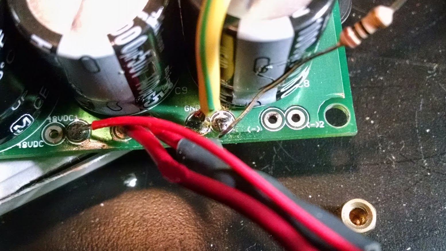
IMG_20150414_194008499.jpg


And this is the ground routed from GND to a post on the chassis, to the wall outlet ground.
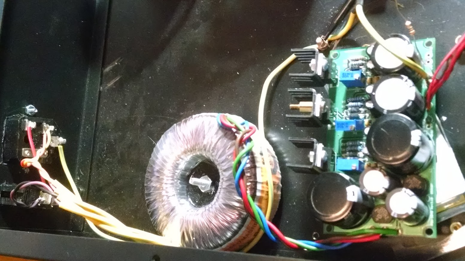
IMG_20150414_194110819.jpg


With the COM lead of my DMM clipped to the chassis, I measure 4.5MΩ at the GND pad for both connections.  :eek:

(time passes....)

OK looks like my 10Ω resistor burned out - it's reading 9MΩ.

So, assuming I have a good 10Ω resistor hanging out - is this wired up correctly?

Thanks for the help!
 
Getting closer ...  when I have channel "A" tied into the ground, I measure 10Ω from 0v to chassis ground.  When I have channel "B" tied into the ground, I get 3.9MΩ.  So... I'm guessing that means something has shorted out or is otherwise busted on channel "B"?
 
mtw said:
Getting closer ...  when I have channel "A" tied into the ground, I measure 10Ω from 0v to chassis ground.  When I have channel "B" tied into the ground, I get 3.9MΩ.  So... I'm guessing that means something has shorted out or is otherwise busted on channel "B"?

Yes, it seems you should re-check channel B.
Check for tracings touching under the board, check for metal standoffs touching traces or components under the boards

I asked you before but you didnt reply,
whats the diference of 0V on the PSU and the PSU GND?

Is the the PSU GND the connection to the Chassis?

Normally only all the 0V chould connect to one point in the PSU, then from that point only one wire and one wire only connects the 0V to the Earth Connection trough a 10ohms resistor, normally a point in the chassis.
you said you have multiple wires, but you should only have one "I have individual leads to each 0v pad, the end of those leads are soldered to a 10Ohm resistor"

Is it possible that there's already on the PSU PCB itself a 10ohm resistor connecting between 0V and the GND pad?
Please measure resistency between the 0V Pad and the GND pad, without having the PSU screwed into the standoffs.
If the 10ohm resistor is already on the PCB then theres 2 ways, or the GND PAd is also connected to the one of the standoffs holes and that way the metal standoff will connect GND to the Metal Chassis (The JLM PSU is like this) or you need a simple wire from GND PSU to EARTH Ground


Whoops said:
mtw said:
Getting closer ...  when I have channel "A" tied into the ground, I measure 10Ω from 0v to chassis ground.  When I have channel "B" tied into the ground, I get 3.9MΩ.  So... I'm guessing that means something has shorted out or is otherwise busted on channel "B"?
Yes, it seems you should re-check channel B.
Check for tracings touching under the board, check for metal standoffs touching traces or components under the boards
will do!
Whoops said:
I asked you before but you didnt reply,
whats the diference of 0V on the PSU and the PSU GND?
Well that's what's been confusing to me this whole time: there is no 0V on the PSU.  I've got pads for +48V, GND, +24V and -24V.
Whoops said:
Is the the PSU GND the connection to the Chassis?
yes
Whoops said:
Normally only all the 0V chould connect to one point in the PSU, then from that point only one wire and one wire only connects the 0V to the Earth Connection trough a 10ohms resistor, normally a point in the chassis.
you said you have multiple wires, but you should only have one "I have individual leads to each 0v pad, the end of those leads are soldered to a 10Ohm resistor"
I did a poor job describing what I've done.  I've got one lead from channel "A" 0V and one lead from channel "B" 0V tied into a 10Ω resistor.  That resistor is soldered into one of the PSU GND pads.  The other PSU GND pad is used for the chassis ground.
Whoops said:
Is it possible that there's already on the PSU PCB itself a 10ohm resistor connecting between 0V and the GND pad?
Please measure resistency between the 0V Pad and the GND pad, without having the PSU screwed into the standoffs.
So this is what has me wondering if this PSU will work. I've only got 2x48V, 2xGND, 2x-24V and 2x+24V  :eek:
 
mtw said:
Whoops said:
mtw said:
Getting closer ...  when I have channel "A" tied into the ground, I measure 10Ω from 0v to chassis ground.  When I have channel "B" tied into the ground, I get 3.9MΩ.  So... I'm guessing that means something has shorted out or is otherwise busted on channel "B"?
Yes, it seems you should re-check channel B.
Check for tracings touching under the board, check for metal standoffs touching traces or components under the boards
will do!
Whoops said:
I asked you before but you didnt reply,
whats the diference of 0V on the PSU and the PSU GND?
Well that's what's been confusing to me this whole time: there is no 0V on the PSU.  I've got pads for +48V, GND, +24V and -24V.
Whoops said:
Is the the PSU GND the connection to the Chassis?
yes
Whoops said:
Normally only all the 0V chould connect to one point in the PSU, then from that point only one wire and one wire only connects the 0V to the Earth Connection trough a 10ohms resistor, normally a point in the chassis.
you said you have multiple wires, but you should only have one "I have individual leads to each 0v pad, the end of those leads are soldered to a 10Ohm resistor"
I did a poor job describing what I've done.  I've got one lead from channel "A" 0V and one lead from channel "B" 0V tied into a 10Ω resistor.  That resistor is soldered into one of the PSU GND pads.  The other PSU GND pad is used for the chassis ground.
Whoops said:
Is it possible that there's already on the PSU PCB itself a 10ohm resistor connecting between 0V and the GND pad?
Please measure resistency between the 0V Pad and the GND pad, without having the PSU screwed into the standoffs.
So this is what has me wondering if this PSU will work. I've only got 2x48V, 2xGND, 2x-24V and 2x+24V  :eek:

You got the wiring wrong, should be like this:

0V of the Boards wired to the PSU GND, the PSU GND connects with to Earth GND (Chassis) through a 10Ohms resistor.

Please read the Posts, I already told you that there's not nothing wrong with the PSU

"I don't think you've chosen the wrong PSU, You need +24V at aprox 1 Amp for 2 channels, so that PSU should work fine"

Check if the PSU GND pad is connected to any cooper ring around the Standoff holes on the PSU, and if so measure resistance between Cooper ring and GND Pad.


Whoops said:
Yes, it seems you should re-check channel B.
Check for tracings touching under the board, check for metal standoffs touching traces or components under the boards

Wow - serious rookie mistake here.  I was measuring ground with an XLR cable connected into my recording interface. ::)
Whoops said:
You got the wiring wrong, should be like this:

0V of the Boards wired to the PSU GND, the PSU GND connects with to Earth GND (Chassis) through a 10Ohms resistor.
And the culprit is found!  I had originally wired up everything this way and, after reading your post, put it back the way it was.

I was still reading incorrect resistance between 0V and GND (even after unplugging all XLR cables).  I decided to start from the beginning and take everything apart.  I measured the 10Ω resistor just to make sure - it was totally fried, reading 4MΩ.  I had originally used a 1/4 watt resistor thinking I could get away with.  Apparently not!! I replaced it with a 1W and everything is back to normal.

thanks for your help Whoops!
 
Hello,
I have a pertinent question to ask you all.

When measuring transistors for this circuit is often referred that at least the first transistors in the darling config should have an HFE above 600.
It's also noted in different places that Neve did the same selection.

My question is this HFE above 600 is measured at what base current?

I have 3 different devices to measure HFE, all of them give different values.
The DMM has sockets to measure HFE, it gives me a number for the beta although I dont know in this case the Base current.

Also I have the Peak DCA75 and it gives another HFE value and it says there the collector current and base current is 5mA

I also have another device where I can have measurements of the HFE at different base currents 10uA, 1mA, 10mA, ....
It's the DUOYI DY294 Digital Transistor Tester / Semiconductor Tester

The same transistor in the peak at 5mA base current reads 578 HFE, when I measure it in the DY294 at 10mA it reads 167 HFE and 550 at 1uA. This is strange how can almost the same HFE value be measured in one unit at 5mA and another at 10uA?

So whats the value that's relevant?
What would be the base current used by Neve to measure and select transistors above 600 HFE?

Thank you
 
Re: HFE testing:

You want to select one meter, and pick out, say, ten BC184's. Then use whichever has the highest HFE as the first transistor in the Darlington configuration.  Meter readings vary wildly as you've noticed, so just compare sets of transistors. However, the whole process is a bit academic and you probably won't notice a difference IMHO. I am not sure which base current Neve used.

M.
 
Hello, everybody!

So after spending months acquiring parts and working on a four channel EZ1290, I finally got the chance to finish wiring it up. But when I passed signal through, nothing came out. Super, super frustrating, especially since I took my time to make sure nothing got misplaced. So I started to go through to check voltages and what nots and found some significant differences compared to the provided Transistor voltage page. 3 of the 4 boards showed 10.27, 3.1, and 2.4 for TR1 and 19.5, 10.26, and 19 (C,B,E respectively). The fourth showed 5.4, 0, and 0 for TR1 and 4.7, 5.4, and 4.7 for TR2. I realize that the fourth one probably has some classic cold solder joint-itis, but I am not sure about the other 3. I already found that the trimmer pot has been wired incorrectly, so I'm going to pull it out for the time being and put a jumper in to aid in trouble shooting. I measured the test signal coming into the preamp after the transformer and it is indeed adding +6 dB (VTB9045 wired in series). I can trace the voltage to the corresponding gain switch resistor, then loose it after that. I think.

I know that simple and ridiculous has been overlooked and/or messed up on my end, but after spending all the time I have trying to put this together, I sure would appreciate any assistance pointing me in the right direction. I'm dying to try them out with my CAPI preamps on drums.

Thanks!

Paul
 
Quick update:

I had found a broken resistor leg which seemed very odd, so I repaired it and have managed to pass signal through it. While running pink noise, I found the signal jumps dramatically when adjusting the gain switch, or if I just adjust the level of the signal feeding it. Also, there is what sounds like popcorn popping when I increase level.

Getting closer!


Paul
 
Hi All,

I'm just about to start my 1290, but I'm having trouble finding a couple of parts.

The following show up as obsolete, and I haven't been able to find them.

C9 Mouser 75-225P400V0.01 Capacitor Polyester Film .01uF
C9 Mouser 23PS110 Capacitor Polystyrene 100p

Does anyone know of a safe alternative or somewhere these can be sourced?

Thanks for any help!

Mike

 
mikeaude said:
Hi All,

I'm just about to start my 1290, but I'm having trouble finding a couple of parts.

The following show up as obsolete, and I haven't been able to find them.

C9 Mouser 75-225P400V0.01 Capacitor Polyester Film .01uF
C9 Mouser 23PS110 Capacitor Polystyrene 100p

Does anyone know of a safe alternative or somewhere these can be sourced?

Thanks for any help!

Mike

Try these for Polyster:

http://www.mouser.com/Passive-Components/Capacitors/Film-Capacitors/_/N-9x371?P=1z0wpzoZ1z0z819Z1z0z7l5Z1z0x6fvZ1yznbzr&Keyword=0.01+uF+polyester+capacitor&FS=True

Just make sure there will be enough lead to reach the solder pads. Double check their voltage ratings agains the one that is obsolete.

For polystyrene it just go to http://www.justradios.com/cart.html. Scroll towards the bottom and they are on the right side. They have pretty much all the polystyrene caps you're going to need. I haven't been able to find any on Mouser.

Paul

 
Hello again, everyone.

So, when I started putting all this together months ago, I somehow ordered MJ2955 transistors (PNP) and not 2n3055 (NPN) and I installed them without double checking. I feel really, really silly. I still have the one card that has very different voltages on the BC184C's in the driver stage than the other one's.

I'll get the new transistors in go from there.

I'm still amazed how long it takes me to find the obvious mistakes.


Paul
 
Thanks so much, Paul!  I found the C9  Mouser  23PS110  Capacitor Polystyrene 100p  on eBay, and I'm going to check into the alternate  Polyester Film cap you suggested. 

I had to get the 2n3055 from ebay, too.  Good luck with your build!

All the best,

Mike

 
Hey guys, just wanted to give a heads up there's a new revision of the EZ1290 PCB (& BOM) around the corner that will alleviate some of these capacitor woes. Stay tuned!  ;)

M.
 

Latest posts

Back
Top