Does audio generally pass through the front panel knobs/switches in an Equaliser?

GroupDIY Audio Forum

Help Support GroupDIY Audio Forum:

This site may earn a commission from merchant affiliate links, including eBay, Amazon, and others.

canidoit

Well-known member
Joined
Apr 6, 2009
Messages
1,174
Location
Australia
When EQ designers build a parametric equaliser and they have 2 PCBs, one PCB that has all the front panel knobs and switches to make adjustments, and then they have a main PCB, where its connected to the XLR ins/outs, transformers, etc.

When you connect the PCBs together via ribbon cable, like below, is the audio fed to the front panel PCBs or are they sort of like controller signals being sent back and forth between the 2 PCBs?
wesaudio_leqp_02-dR_Pt7Js_HPWt87PxNcuokkIDG2oO6gh.jpg

I am trying to add a pre and post EQ insert and I am considering hijacking the audio signal fed through the ribbon cable.
 
I guess that might depend on the particular EQ you're looking at. No way of knowing a priori, you'd need to trace it out or have a detailed schematic.

The EQ you've put a pic of looks like a Pultec-style passive EQ with tube makeup, rather than active parametric. In that particular EQ, it looks like the signal would be constantly back and forth between control PCB and main PCB per each filter section.
 
Thanks for the replies. John, do you mean there is audio signal but the audio is too low to grab from there?

@Twenty, it is actually not the pultec in the pic, but a different EQ below, which has M/S feature. I want to utilise the M/S functionality from it, by hijacking the signal after it encodes it and feed it back to decode it. Add some DIY inserts to the unit. I was thinking, maybe there is audio signal that feeds the M/S PCB button on the front panel?
eq-mod-labelled.jpg
 
Needs schematics indeed.

As John suggested, it's more complicated than 'just' adding a few wires hooked to some input and output jacks.

Splitting signal off MIGHT be as easy as a wire to the correct resistor lead. However, very likely you need output drivers, input buffers, maybe even summing stages.

By that time ,is it not better to build a dedicated MS encode/decoder box!?
 
I agree with Script. You might be able to hack something in here, but it would be a hack. It would likely be impossible to do it cleanly, and (depending what this EQ is) could devalue the unit more than the difference in cost of building a standalone high quality mid side matrix using something like this.

Depending on your workflow, if digital matrixing is an option then I highly recommend Voxengo's free MSED plugin.
 
Thanks for the replies. John, do you mean there is audio signal but the audio is too low to grab from there?
The first parametric kit (P-94) that I published in 1979 used ribbon cables to connect to the front panel mounted pots. The signals inside those ribbon cables were connecting to sundry nodes in the state variable filters that made up the EQ.

SO not suitable for I/O.

JR
 
Edit:
Not thinking straight re no decoder for M/S below!

Neither of the two pics posted appear to have controller chip functions at the front panel - the first being a tube unit has no IC’s that could do controller functions.
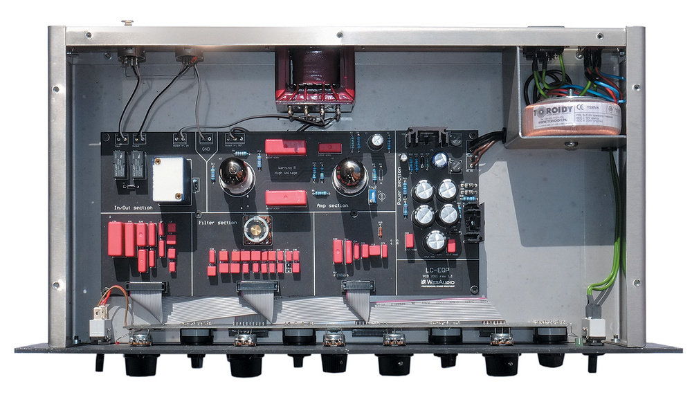
The one you are wanting to use, looking at the front panel control it looks like it may be doing the m/s encode switching via relay logic which is easily done using phase reversal and summing with buffer IC’S - however to hijack the signal you would need to feed the output of each buffer stage to an IC capable of driving an insert send and then a receiver to bring the signal back in from the insert return. You would also need to cut the connection link at the switch insertion point so you don’t end up with both insert and thru signal mixed. A schematic is essential to do a design that would make this easy.

Delete: (However - the BIG but here - this unit will only have the encoder - no decoder. As this EQ does separate EQ on mid and side or left and right - (looking from above it is a dual EQ, so I would assume so, otherwise there would be little point in having an m/s switch) the switch encodes pre EQ and has no need for a decoder!)

As an external device a simple mixer with phase reverse switches on each channel and 4 assignable subgroup outs you can make your own M/S encoder/decoder.

Encoding M/S Signal:
3 channels needed with
Ch1 Left signal coming in
Ch2 Right signal coming in
Ch3 Right signal coming in - you can use a parallel link input cable (or use a Group send from Ch2 into Ch3 input but the two channels need to be at identical levels).
Ch1 assigned to Group 1 and Group 3
Ch2 assigned to Group 1
Ch3 assigned to Group 3 phase invert sw engaged
Do not assign these 3 to Main mix out.

Group 1 out (encode/send) = Mid = Ch1+Ch2 sum Left+Right
Group 3 out (encode/send) = Side = Ch1+Ch3 diff Left-Right (Phase inverted Right Channel means we get difference between original Left and Right channels).
I have used Groups 1 & 3 as a lot of smaller mixers have groups allocated to buttons in pairs using pan left for odd, pan right for even so in this case pan Ch1 x Ch3 left. If using a mixer with a separate switch for each individual group the pan rule still usually applies.
The two Group output faders should be set at -6dB (or the three channel faders at -3dB) as the summing increases the signal levels.
L-R to M-SM-S to L-R
M = L+RL output = M+S = (L+R)+(L-R) = 2L
S = L-RR output = M-S = (L+R)-(L-R) = 2R

Decoding M/S signal:
Ch4 Mid (return/decode) signal coming in. Panned to centre, assigned to Main
Ch5 Side (return/decode) signal panned left, assigned to main
Ch6 Side (return/decode) signal panned right, phase invert sw engaged, assigned to Main. Once again you will need a parallel split cable for the return to link 5 and 6 inputs.
All faders set to -3dB.
Left Channel = sum Mid+Side
Right Channel = difference Mid-Side

The software M/S encoders and decoders do exactly the same thing.
You can also buy purpose built encoder/decoders.
 
Last edited:
Thanks everyone for their replies!

I was thinking maybe I can utilise the M/S features more from this Bandxall style EQ, as sometimes I may want to compress or do more surgical EQ than do its standard limited Bandxall EQ with the M/S. Also save some money and time if I can hack the M/S :)

I was hoping the ribbon cable was my ticket to extracting the M/S, so that I can just make a modified ribbon cable (wired to jack/XLR sockets) that I use when I own the unit, and when its time to sell, I just put the old ribbon back in.

Are there are any sonic differences between analogue and digital M/S - ie. noisier, harmonics, can the analogue M/S decoding produce variances that could be conceived as musical?
 
It would be significantly more involved than just swapping out ribbon cables unfortunately.

Digital M/S should be theoretically more accurate (more transparent) than analogue, though the Ka Electronics matrixes are about as good as you can get in analogue and are very clean. Personally I'd look elsewhere in the signal chain for mojo.

@RoadrunnerOZ - if this EQ had no M/S decoder, wouldn't that mean the signal on the output XLRs in M/S mode would still be matrixed (ie left XLR carries mid signal, right XLR carries side)? I've built several EQs with M/S capability, and have always had to include both encoder and decoder.
Yeah good point - my slip there not thinking properly. Spent too long in software plug-in land and fixing gear.
So the encode will be at the input and decode at the output of the whole EQ stage. Makes for an even harder hack.
 
Thanks everyone for their replies!

I was thinking maybe I can utilise the M/S features more from this Bandxall style EQ, as sometimes I may want to compress or do more surgical EQ than do its standard limited Bandxall EQ with the M/S. Also save some money and time if I can hack the M/S :)

I was hoping the ribbon cable was my ticket to extracting the M/S, so that I can just make a modified ribbon cable (wired to jack/XLR sockets) that I use when I own the unit, and when its time to sell, I just put the old ribbon back in.

Are there are any sonic differences between analogue and digital M/S - ie. noisier, harmonics, can the analogue M/S decoding produce variances that could be conceived as musical?
Sorry about my slip in my earlier post re no decode of the M/S.

Without seeing the M/S switch board it would appear that it is just a switch driving a couple of what seem to be relays on the main board and that all M/S encode/decode is done there. I doubt there’s any audio wiring in the switch ribbon.
The other thing you would need to consider if hijacking the M/S, is where the EQ would fit into the chain - if you lift the M/S encoded input from the EQ to feed M/S externally there’s no input to the EQ any more, similarly lifting the EQ output to insert a return from external device(s) for M/S decoding leaves the EQ output out of the chain. If you wanted to include the EQ as part of the M/S chain this would involve some fancy switching/wiring - especially regarding external devices being pre or post EQ if you wanted the choice.
Do you have any schematic for this unit?
 

Latest posts

Back
Top