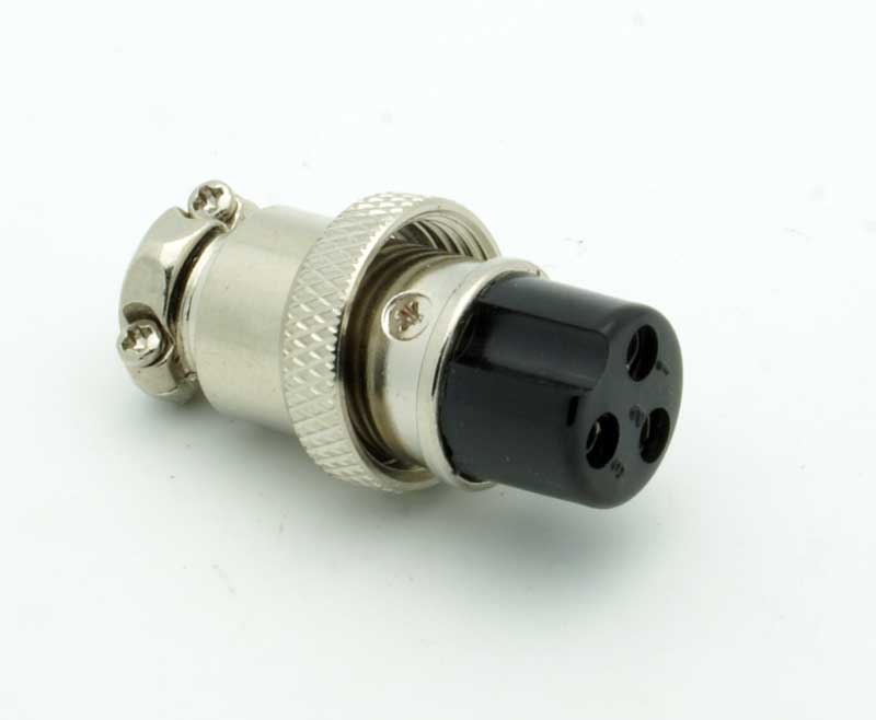
Hey guys! Probably it was answered before but couldn't find exactly where. When you separate PSU why would you need 4 cable XLR?
1. +24V
2.0
3. +48v
What is 4-th used for?
1. +24V
2.0
3. +48v
What is 4-th used for?
Olegarich said:Hey guys! Probably it was answered before but couldn't find exactly where. When you separate PSU why would you need 4 cable XLR?
1. +24V
2.0
3. +48v
What is 4-th used for?
tomnyhbees said:Hi,
I’m having a little issue getting 48v to work independently for 2 channels. When 48v is on for one channel the other channel gets power as well. At this point both channels are showing 33v. Only when I turn 48v on for both channels do I get 48v. Anyone else have this issue? What have I missed? Thank you
Hard wiring.Potato Cakes said:Are you hard wiring it or using a JLM Go Between?
Thanks!
Paul
Olegarich said:Hey guys! Probably it was answered before but couldn't find exactly where. When you separate PSU why would you need 4 cable XLR?
1. +24V
2.0
3. +48v
What is 4-th used for?


Potato Cakes said:Are you hard wiring it or using a JLM Go Between?
Thanks!
Paul
tomnyhbees said:The issue is the Neutrik metal connectors are conducting. So that means the entire enclosure is getting 48v.
tomnyhbees said:The issue is the Neutrik metal connectors are conducting. So that means the entire enclosure is getting 48v.
tomnyhbees said:The issue is the Neutrik metal connectors are conducting. So that means the entire enclosure is getting 48v.
Potato Cakes said:You should see +48V as referenced to 0V which ultimately should tie to a star ground point, which will be the chassis. But Pin 2 and 3 of the XLR should not have any continuity with the chassis, which is where you should have +48VDC from the phantom power switch connected via two 6k8 divider resistors.
I think you just need to do a thorough continuity test to see if you have any shorts. And also make sure that you are getting +48V at all of your phantom power switch poles when they are in the off position.
Thanks!
Paul
tomnyhbees said:I thought I had a problem with the xlr connectors, but the problem was with the 1/4 inputs I added. The tip was connected to the input transformer, which was connected to xlr input pin 3. Obviously an oversite on my part. Thankfully the issue has been resolved and everything works great and sounds great.
That correct, sleeve not pin. ThanksWhoops said:That mistake would not put 48V on the case, the tip should be connected to pin2, so what it could do is invert the polarity of the signal.
If you had 48V on the case then you connected the jack "Sleeve" (and not the tip) to Pin3
digistu said:All four channels have worked quite happily for some time, but recently I unintentionally left the unit powered on (with phantom applied to one channel) overnight.
digistu said:I wondered if leaving the unit powered on for so long might have cooked the polyester capacitor at C2, so I've replaced with a modern Wima, but no difference.
Enter your email address to join: