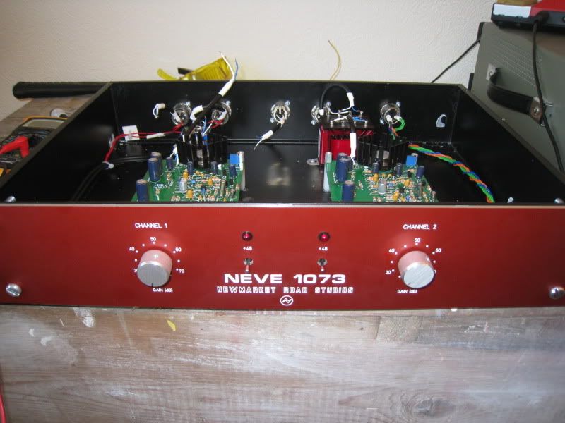
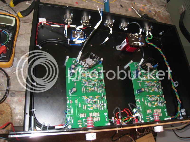
8 Channel, 3U NEVE 1073 completed

GroupDIY Audio Forum

Help Support GroupDIY Audio Forum:

This site may earn a commission from merchant affiliate links, including eBay, Amazon, and others.
Hi Martin,

I have used shielded wire, but I didnt connect the shield to the pad on the output, Instead I just connected a separate wire from pin 1 on the XLR to that pad. After reading a bit more about how shielding works, I realize this is not an appropriate solution and Im thinking this may be the cause of my oscillation.

Have you connected the shield to pin 1 at all, or is it ok to terminate at the LO1166?

Thanks again!
Jake

 
Hello all! is there anyone here that can post some schematic drawing for a vocal's hipass filter (around 100hz) that can be used in this project or in another preamp wiring?
Where shoul I wire that? on the input on the output of the preamp?
Thanks a lot!!!!
Keep on with the great work martin ;) i'll order more boards soon :)
Cheers!!

Eddie :)
 
snipsnip said:
Hi Martin,

I have used shielded wire, but I didnt connect the shield to the pad on the output, Instead I just connected a separate wire from pin 1 on the XLR to that pad. After reading a bit more about how shielding works, I realize this is not an appropriate solution and Im thinking this may be the cause of my oscillation.

Have you connected the shield to pin 1 at all, or is it ok to terminate at the LO1166?

Thanks again!
Jake

Hey Jake. Just read your posts. IMO I'd say just follow Martin's build guide for the i/p o/p xformers. I did that and I got 4 pairs up and running! There's no ground on the o/p XLR. Also, maybe post some pics when you get a chance. You can see pics of my first pair here:

http://www.groupdiy.com/index.php?topic=20152.320

These worked fine so you can get an idea. I used Canare quad cable (a twisted pair for hot and cold) but I just did this because I had a bunch of it. I'm sure it's overkill. Any high quality standard mic cable (mogami, canare, gotham, etc.) is fine. Hope this helps!

Dan.
 
Cheers Dan,

Yeah I was just a bit confused by the assembly guide as there it says only use pin 1 for shield, but nobody seems to have connected this in their pics.

I guess you just leave this disconnected.

Yours looks nice BTW!

Thanks
 
As requested, here are some pics of my progress so far.

Only the right channel hooked up as my other transformers have had to go back for testing as they didnt work.

I redid the output with shield connected, but still get some oscillation.

Martin - Im looking at resistors around the gain switch again. I notice a couple of them are marked '12k0' etc. Is this different from 12k? I assume is just means 12k, but notice it is a different naming convention from the rest of the board.

IMG_3068.jpg

IMG_3065.jpg
 
Hi
I was just wondering what kind of standoffs to use for the pcb metal or plastic?
The mounting hole near the 5k trimmer is part of the circuit ground so should it
make contact with the case?


madriaanse said:
Hi Snipsnip, yes that sounds like oscillation. This is usually caused by:
A. not using shielded wire
B. running mic input wires too close to line output wires
C. having the 10468 (VTB9045) too close to LO1166 (VTB9049)
D. malfunctioning 2N3055

Also, double, triple, quadruple check the resistors values around the gain switch.

Hope this helps,

M.

Hi Martin, (or any kind soul)

Ive got all both channels working, but face the oscillation issue on both.

my input and output transformers arent very close (as per photos), and the wires arent close at all.

I have used shielded wire (however I havent taken the shield to pin 1 on the XLR - do I need to do this?)

Im guessing both TR3's being faulty i highly unlikely?

Ive also checked all the resistors where I still have spares and have matched the colours. They all seem OK. Again, Im not sure if the 18KO and 12KO are different to a normal 12/18k resistor?

As I mentioned before, even with no input signal, and no speakers turned on, you can hear the noise coming from the transformer itself with high enough gain setting.

Really appreciate ideas from anybody!

Thanks a lot
Jake
 
Hi Jake, since no one answered you on the 12K0 etc. yes its same as 12K. I had the same exact same oscillation on my 2 EZ1290s when I first hooked them up. I could actually hear a tone about 1KHZ.

I don't remember exactly what I did to make it go away. Have you set your trimmer as per Martin's instructions? I think that's what it was.

My XLR's pin 1 are all connected together and then to a star ground point. Power Supply ground also goes there. When you are testing I would recommend totally removing the second unit from any common connections (in case you have some ground loops). Just isolate and work on one board at a time.

If you have an oscilloscope verify you don't have any AC ripple in the DC.

Jim
 
Hey Jim,

Thanks a lot for the response, really appreciate it.

Ive had a random twiddle of the 5k trimpot to no avail, but I havent had a proper look with the scope.

I'll also check for ripple in the power whilst Ive got it set up.

I'll let you know how I get on. Thanks again!
Jake
 
What psu are you using? IF theres a small ripple on the psu you'd be able to hear it on the preamp!
Hey its that a LEADER scope? i have the same!
 
snipsnip,

Sorry for the delayed response. Work's got me so tied up it's not even funny. I don't see the drain (shield) wire connected on the shielded cable going from PCB to your input transformer?

M.
 
Hi martin,

No worries on the delayed response, Im greatfull for any help and am more than happy to wait a few days!  ;D

You know what, you are absolutely right, I think I used a 3rd wire on the canare rather than the shield (as per one of my earlier posts I didnt really understand shielding until recently) and I had totally forgotten thats how you spec'd the input wiring in the guide!

I'll give this a go when I get home, as well as looking for ripple. (BTW 3nity - Im using a JLM ACDC, and my scope is an old hitachi one.. cheapest I could find!!)

Thanks a lot guys,
I'll let you know how I get on.
Jake
 
no problem, you might also try mounting the input transformer closer to the PCB - use a longer wire on the balanced side and a shorter wire on the unbalanced connection to the PCB.

m.
 
Hi Madriaanse,

Congratulation for that great work !

I have a small question : where did you get the metal plates where each PCB is mounted on ? I need some for my 8 Green and I did an estimation at FPE, but 10€ for a piece of blank metal is quite expensive ! Besides I don't need it to be aluminium, steel would be just fine for that use.

Thanx in advance.

Best regards.
 
Back
Top