A couple 1176 parts questions

GroupDIY Audio Forum

Help Support GroupDIY Audio Forum:

This site may earn a commission from merchant affiliate links, including eBay, Amazon, and others.

matta

Well-known member
Joined
Jan 11, 2005
Messages
1,640
Location
Cape Town, South Africa
Hey Guys,

I'm steadily making my way through my Mnats 1176 and have come to a few obstacles and need some advise.

1.For the 2K trimpots can I get away with a 2K2 one as this is what the local store has in stock?
2.For the 38.3K resistor can I substitute a 39K?
3.For 44K2 can I use 44K or 45K?
4.For the 4R3 resistors can I use metal film over carbon, though the BOM calls for Carbon?
5.Any common value substitute for 7K68

Thanks in advance, I'm quite excited about this one :thumb:

Cheers

Matt
 
cant see any reason why you would have to use a carbon film over a metal film.. I'd go with metal film

as for the resistors.. if you need precise values then put a few in series.. such as a 38k and a 300 ohm in series..

odds are the tolerance percentage allows for some discrepencies

toss em in there

it aint rocket science :green:
 
Thanks Scenaria,

Sometimes I feel like it is rocket science, I'm still in fringed Newbie stage, like veering off a few ohms will make my projects blow up into little pieces and I'll be left on the floor in tears :green:

I had thought about the precision aspect, having the resistors in series, doesn't look as nice though, but maybe I'm being picky, LOL

Thanks for taking the time to respond.

Anyone used a common value and powered up, had it work and no bits and pieces across the room :grin:

Cheers

Matt
 
Okay...

This might not be rocket science but I just want to check these values.

I have used the flowing:

r66 = 182k -> 179.1k
r67 = 38.3k -> 38.6k
r69 = 44.2k -> 42.6k
r71 = 7.68k -> 7.44k

The first number being the BOM/Schemo value, the second being what I used in it's place, those are the exact reading I got prior to putting them on the board from my DMM.

Do you think these substitutions will be safe?

Thanks

Matt
 
Hah hah!

So do I pass the NASA resistor test! LOL Man I am getting there, my DIY has been cut so it would prob take a month to get done, down to the meter, audio trano and pots, these things are not too cheap in Africa :shock:

But looking forward to powering up, in the meantime I'll be starting my SSL Buss Comp

Thanks again for all the help.

Cheers

Matt
 
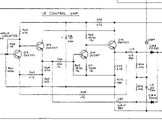
I've just been revisiting this problem of sourcing these odd values after running out of some of them and finding the local stores don't stock these precise values. On some of the schematics I have seen these are the only resistors marked 1% on the drawing while on earlier drawings it appears they selected parallel values to trim the circuit. So I tried to figure out why...corrections welcome as always.


Click for a bigger image.

Audio enters the GR Control Amp, goes through the first two-stage amp, the DC component of the output gets blocked by the capacitor and half the waveform gets rectified. Just before the capacitor the signal is tapped off into a voltage divider made up of the first pair of 1% resistors R66 and R67. About 0.174 of the input voltage to the divider appears across R67. The voltage gain of the inverting amplifier Q14 is determined by the second pair of 1% resistors giving a gain of about 5.76. So the waveform gets inverted and the total voltage gain is 0.174 x 5.76 or 1. That way there can't be any error introduced into the other half of your input waveform. After that it goes to the second current gain stage just like the first section and off to the rectifier to turn into lumpy DC.

Matt's substitutions give a gain of about 1.015. Other possible substitutions for R66, R67, R69 and R71 with common values are:

180k, 39k, 43k and 7.5k - gain 1.02
180k, 36k, 43k and 7.3k - gain 0.98

So as usual Jakob is right - not much to worry about. Though it seems like the designers thought it was important to be very precise...
 

Latest posts

Back
Top