A multi-purpose PCB: Mic preamps, summing amps, line channels, mixer..?

GroupDIY Audio Forum

Help Support GroupDIY Audio Forum:

This site may earn a commission from merchant affiliate links, including eBay, Amazon, and others.
Ok, getting somewhere with the transformers:


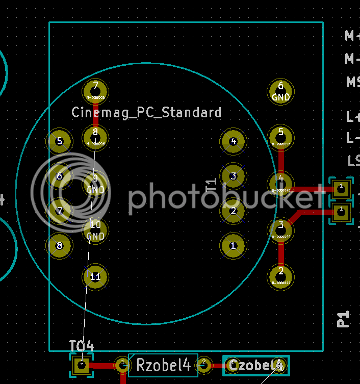
So, the large square one will fit a Carnhill VTB9045M (for mic input) or VTB9046M (for line input); Each primary & secondary wired in parallel for both transformers, which makes it easy

The round one, as Ian said, is good for Cinemag CMMI-3.5APC for mic input and CMLI-15/15PCA for line input. The data sheets are not very clear on the wiring for these. From the datasheet, pins 1 and 4 are the inputs. I guess that means 3 and 2 are wired together for both line and mic transformers?
 
ramshackles said:
The round one, as Ian said, is good for Cinemag CMMI-3.5APC for mic input and CMLI-15/15PCA for line input. The data sheets are not very clear on the wiring for these. From the datasheet, pins 1 and 4 are the inputs. I guess that means 3 and 2 are wired together for both line and mic transformers?

Audio transformer manufacturers all seem to be quite adept at ambiguous pin numbering in their data sheets. If you are lucky you might even get shown where pin 1 is. But you are never sure if the second row goes 4 to 8 or 8 to 4. And the you need to remember they show the pin out looking from underneath the transformer and your footprint needs to be looking from the top.

So many ways to make a mistake.

Cheers

Ian
 
Yes indeed...in fact, carnhill shows the pin layout as a PCB layout and cinemag shows it has a view from the bottom of the transformer.

Carnhill give a nice schematic of their transformers, so it is at least fairly ok to work out how to wire them.
Cinemag only include 5 or 6 of the pins in their schematics  :eek:, as do Jensen. Maybe it's an american thing...

 
Input transformer options...done. I had to re-route the power traces and they are all a bit higgildy-piggildy now.


So the next thing to do is correct the placement of the DIN connector, which looks like it is too close to the lower edge of the board, and then go through all the build options and see if the amp-stages can be 'streamlined' abit. I'm sure that on 1 or 2 of the stages at least, some components can be removed with no effect.
 
Ok. I updated the board layout a bit to improve the routing of the power traces and ordered a few prototypes

What could be cool in the future would be a eurocard A/D converter which takes the buses as inputs...hmmm
 
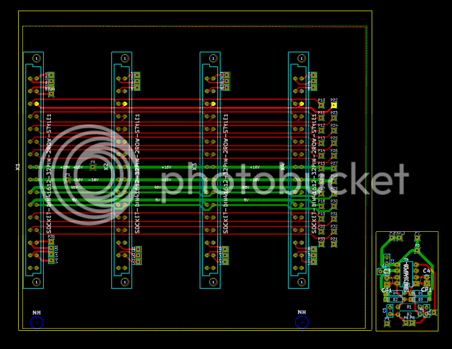
The prototype pcbs are unlikely to arrive til the new year, so I've made tentative steps on a backplane layout.
4 module widths, assuming you use 7HP modules. Theres no reason why you couldn't use a 14HP wide module though, and just miss out every 2nd DIN.


My problem now is that I have a lot of seperate grounds:
Audio
48V - 0V
5V - 0V
The XLR inputs also have their screens brought to the DIN connector.

So at some point these all need to come together. The problem is how? Is this something I should provide a mechanism for on-board (and how?) or should I simply provide enough 'breakout' pads so a builder could make their own decision?
 
Thanks - I knew I'd read this some time ago but forgot where it came from. I think I'll link to it on my website as it is essential reading...

So at the moment, I'm sort of on the right track: Everything is seperate.

I think I understand it as such:
  • My input/output screens (on the XLR's) would be connected directly to the chassis of the audio equipment. This connection is there whether or not I run a screened cable to the output transformer
  • In the case of the input, I need to run a screened cable from the XLR to the backplane so that the phantom 0V can connect directly to it. So I do not need a bus on the backplane for phantom 0V as it goes directly to the input screen and the XLR pin 1. This is still  connected directly to the chassis. If I was not using phantom power (such as for a line input), I'd just leave the transformer end of the cable screen unconnected
  • On the output XLR, I leave the transformer end of the screened cable unconnected. The XLR end is connected to pin 1, which is connected to the audio chassis.
  • The incoming chassis connection from the PSU (which simply goes directly to the common point in the PSU) is also connected directly to the audio equipment chassis


So my PSU needs to accomodate the 5V signal ground, audio signal ground, phantom signal ground and audio chassis connection, which will then all be brought together at the common point in the PSU.

I came a little unstuck at the last part about unbalanced faders, so I'll need to re-read a couple more times!!
 
Yes, I think you managed to neatly summarise everything in four points. Well done.

The thing about unbalanced internal connections to and from things like faders is that you need to avoid creating ground loops. So any such connection needs to be grounded at one end only. In theory it matters little which end you do it. However, in practice it is generally better to ground at the destination end. This is particularly important for faders. When a fader is fully down you want it to short right across the input of the amp it feeds.  Any series resistance in the ground leg of the fader reduces its off attenuation.  Just one ohm in the ground lead of a 10K pot reduces its maximum off attenuation to 80dB.  The cable between the fader ground leg and the ground of the audio amp it feeds therefore needs to be as low impedance as possible i.e short length and direct.

Cheers

Ian
 
A new backplane?

I think Holger has a backplane, and Ian has a backplane, and maybe even Bruno has a backplane (sounds like the beginning of a christmas song).

Is it possible to use the same backplane, and thereby maybe begin a "standard" with more room than a 500 series?  A little conversation and maybe shared ideas maybe with the other backplane makers.

Just and idea, don't know if it would help.
 
Well, I think the problem would be that the EZtubemixer backplanes have slightly different requirements than this one, especially in terms of power supply. I suppose they could be merged but most likely at the expense of a few buses, which isn't good...

An alternative which I did discuss with Ian before starting was to have a 64 pin connector. This could accomodate both, but the layout becomes very tricky (as would the wiring), and it is difficult to insert/remove modules

One of the main things I wanted to do, as compared to the EZtubemixer, was increase the number of buses available for groups or auxes and try to create something that could be built 'backwards' first (Start off with a monitor section, add a few groups for stereo summing and so on)... This backplane gives you a total of 14 buses, which could be 4 aux's and 5 groups (including the master) for example.

The good thing, IMO, is that both backplanes cover a small number of modules (Ian's covers 2 tube modules and mine would be 2-4, depending on your chosen width), and are to fit the same subracks. So you could potentially mix both within the same system and simply have a 'custom' power supply to cater for it. With that in mind, I suppose I don't really see a reason for doing an 'all-in-one' version.
My personal goal is to come up with some kind of summing mixer where I could have a few simple preamps of the kind I'm doing and a few tube preamps/effects in one neat place :)

Although if you have suggestions as to how it could work I'm all ears...
 
Sorry no ideas for this here. 

I don't know if anyone built a backplane with busses (except Ian's Easy Tube mixer).

I think you are right to choose the DIN connector.  Better density, cheaper and easier to manufacture. (The baadc0de backplane (or bruno2000?) I don' t know if it has busses, but they used card edge connectors.).

So it seems like you are creating a new mixer backplane. And you have 5V on it I see, and are considering support for converters.  I don't know much about that stuff, but you might get some useful comments and avoid pitfalls by publishing the proposed backplane pinout.


Sure. Here is the pinout so far (the numbering has been lost, but all the power and ground labels that are the same are tied together. Everything else is a seperate connection):
 
bruce0 said:
A new backplane?

I think Holger has a backplane, and Ian has a backplane, and maybe even Bruno has a backplane (sounds like the beginning of a christmas song).

Is it possible to use the same backplane, and thereby maybe begin a "standard" with more room than a 500 series?  A little conversation and maybe shared ideas maybe with the other backplane makers.

Just and idea, don't know if it would help.

Just to put this into context, the pin out from my and Holger's backplanes are identical. They are both intended for use on the EZ Tube Mixer project. Holger has added some relays and other stuff specific to his needs. So these two backplanes have high voltages on them and are intended for tube circuits.

Ramshackles' backplane is for his project that provides the 'missing link' in the 500 system. At present you can get any number of mic pres, EQ and dynamics modules that you can plug into a 500 rack. But that's all you get, a rack full of modules. The missing link is the ability to route these onto buses and turn them into a full blown mixer. That's what ramshackles' new backplane and modules aims to do.

Cheers

Ian
 
Ian:

Thanks Ian, I didn't realize that.

So there is a developing standard for DIN connectors in DIN subracks (U's and HP's) for analog mixing with high voltages and summing busses on the backplane(s)  - The Ian/Holger defacto standard.  Love to read a little about that, is the bus architecture (number of summing nodes, balanced unbalanced, etc) laid out somewhere?

And here in this thread we have a developing standard for another mixing backplane with DIN Connectors and Racks that supports +/- 16, + 48V and +5V, and also supports many busses (5LR groups and 4 mono aux?).

It seems that you guys are way ahead of my suggestion.  Already coordinating the specs, so it would be possible to just pick up an make modules.  So sorry if I dragged the thread off course.  Is there a summary of your bus pinout Ian?


I suppose it is typical for busses on a small console to be unbalanced?
I note that Radial Workhorse uses an unbalanced bus.

Is there any advantage to using balanced busses?  I suppose most of the modules in general debalance the signal internally, and routing, mixing, summing is much easier, (I suppose all in the same case noise linkage can be controlled) but have mixers in the past tried keeping the busses balanced, does it make sense on larger mixers?  Or is it typical to keep them all unbalanced (Ian i know you have some experience in mixer design).
 
Bruce:

My and Holger's backplanes are used on the EZ Tube Mixer project and are now being used as the basis if the EZ Tube Lunch Box projects which aims to put all tube channels and all tube simple mixers into a rack mounting or lunch box format. Check out the individual threads:

http://groupdiy.com/index.php?topic=53765.msg686243#msg686243

http://groupdiy.com/index.php?topic=51829.msg658803#msg658803

and the connector pin out is here:

http://www.ianbell.ukfsn.org/EzTubeMixer/docs/EzTubeMixer/EurocardCCTsht4.jpeg

What ramsackles is doing is something completely different but it leverages the idea of using readily available 32pin DIN connectors and low cost 19 inch rack mounting DIN enclosures that are available from many manufacturers to extend the regular 500 series system into a full blown mixer.

Cheers

Ian
 
bruce0 said:
And here in this thread we have a developing standard for another mixing backplane with DIN Connectors and Racks that supports +/- 16, + 48V and +5V, and also supports many busses (5LR groups and 4 mono aux?).

It seems that you guys are way ahead of my suggestion.  Already coordinating the specs, so it would be possible to just pick up an make modules.  So sorry if I dragged the thread off course.  Is there a summary of your bus pinout Ian?


I suppose it is typical for busses on a small console to be unbalanced?
I note that Radial Workhorse uses an unbalanced bus.

Is there any advantage to using balanced busses?  I suppose most of the modules in general debalance the signal internally, and routing, mixing, summing is much easier, (I suppose all in the same case noise linkage can be controlled) but have mixers in the past tried keeping the busses balanced, does it make sense on larger mixers?  Or is it typical to keep them all unbalanced (Ian i know you have some experience in mixer design).

Thats right. Whether the buses are groups, mono or stereo auxes is up to the user at this point as I haven't laid out any signal switching modules yet. 5 groups and 4 auxes seems like a logical layout however.

So what I have at the moment is the back plane layout and a eurocard PCB layout which is essentially 4 amplifiers and 2 input transformers. This could be built as a 2 channel preamp, summing amplifiers or a channel mixer with input trim, post fade amp and active panpot. All controls are hosted off board, so to utilise the buses, you would need to add the relevant switches and/or pots.
Adding utility PCB's to do this is next on my list after building up the prototypes, which should hopefully be arriving soon!

For a fairly small mixer like this would be, I wouldn't see the point in using balanced buses. If you opted for that, you immediately put a max of 3 stereo groups on its capability. You would also need a lot of transformers (or electronic balancing)...

Like the EZtubemixer, there is no requirement to build a mixer; you could go for a 'lunchbox'. I like this about Ian's designs and have a list of modules I'll be making for my first tube 'lunchbox' (Im still plodding along with the first couple)
 
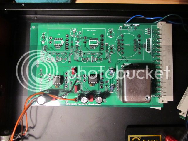
Took a while to finally get all the parts, but I have good voltages on this thing now, just need to connect some connectors and test it...


This board is built up as a preamp, with just one channel populated at the mo. It is the 'el-cheapo' version; IC opamps and a dual pot. I will probably send the output (which is unbalanced) through a THAT chip for balancing...

Once I'm happy with that, I'll try the 'deluxe' version with discrete opamps, switched gain and transformer balanced output...

And then move on to building it as line channels...

There are a few corrections to make before the next batch aswell. The DIN connector footprint is slightly off, pin 1 of the IC's shouldn't be grounded and I think I will include a trimmer to be able to set the offset compensation for IC's as there is plenty of space...
Some things need bigger pads aswell.
It might also be possible to reduce the number of wire links to make on the board (currently 3, plus wiring for the pot, XLR connectors and output transformer/balancing)
 
Back
Top