A multi-purpose PCB: Mic preamps, summing amps, line channels, mixer..?

GroupDIY Audio Forum

Help Support GroupDIY Audio Forum:

This site may earn a commission from merchant affiliate links, including eBay, Amazon, and others.

ramshackles

Well-known member
Joined
Dec 18, 2011
Messages
521
Location
Riorges, France
Hi
I've been working on this idea for a couple of months now.
Heavily inspired by Ian's Eurocard work, and especially the TwinLineAmp, I've set out to make what is essentially the discrete (or IC) version of the same thing. I'm currently calling it...:
QuadLineAmp

Basically, it is 4 amplifiers and 2 transformers on a PCB.
Each amplifier has some associated circuitry, and each amplifier is 'unconnected'.
The idea is, that by connection things up in the right way and varying which components are populated (and their values), you can build a number of things.

I've laid out designs for:
- 2 channel microphone preamp
- Stereo summing amplifiers
- mono summing amps
- a 'Line mixer' with input gain, post fade amp and an active pan pot...this is pretty rough at the moment
- 2 mixer channels with input gain, post fade amp and a pan pot using Ian's smart pan pcb....even more rough..

I *think* I have laid out a PCB so that all of this stuff can be made, either using discrete opamps or 5534 opamps.
Like Ian's designs, the idea here is that all the controls are mounted off-board, making it very configurable.

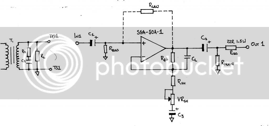
Here is a schematic of a single amp stage, as it is on the PCB:


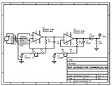
Here is a schematic for a single channel of the mic preamp, with values chosen for NE5534 opamps (to make this nasty pic a bit clearer I omitted the compensation cap, decoupling caps,zobel network and power supply):


Here is a pic of the PCB layout so far:


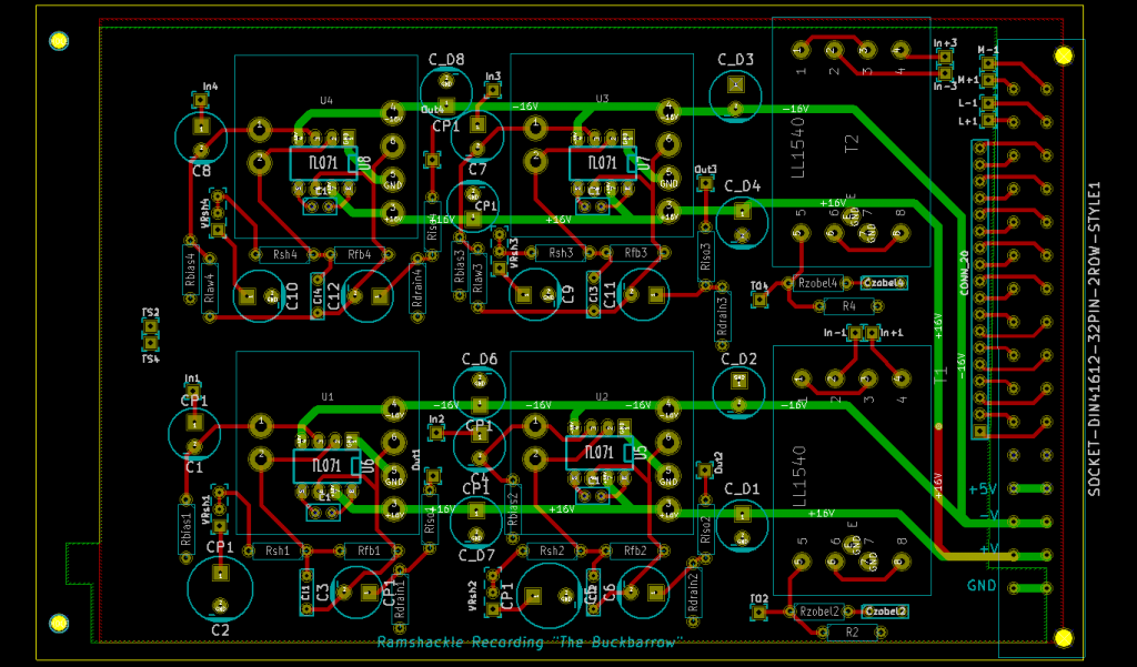
The transformer footprints are LL1528 (for mic input) or LL1527 (for line input). Finally there is a 32 pin DIN connector which will plug into a custom back plane

The backplane will have buses for +/- V, ground and +5V (or whatever for leds/relays/what you like). There are also 2 connections for balanced inputs 2 for unbalanced outputs and then the remainder are given over to buses.

So you could potentially make a mixer (you might need a few little pcb's to host all the controls for aux/group switching). With the active panpots you could probably drive a fair number of groups and then use the same PCB for the summing
 
Excellent start. I suspect people will want some means of fitting alternative transformers. I would be tempted to ground plane the 0V - ooops, you already did.

By the way, what program did you use to draw the mic pre schematic?

Cheers

Ian
 
Hi
Yeah..there is a ground plane on both sides - I just turned off the display so I could see the tracks!

Alternative transformers...I did have a short play a while ago with trying to get an OEP footprint to fit but I wasn't having much luck. I've since rejigged the layout so I should try again.
Sowter and perhaps carnhill might go on, although I would like to find both line and mic transformers which have the same footprint (so they could be interchanged).

I've mentioned the LL1527 as the line transformer...it is advertised as a mic transformer but can be hooked up at 1:1 for line inputs; I don't know how it performs though.

Mic pre schematic: I used 5Spice analysis. Just because I wanted to do a spice simulation but I'm kind of lazy at trying to write the input files by hand. 5Spice is free (well, up to a very small schematic size) and is a simple schematic editor and spice analysis. I've not found any other alternatives that are so simple to use, but it is very limited.

For the pcb layouts, netlists etc I use KiCAD...


I've not inlcuded 48V to the board (although there are 2 pins free on the DIN), nor have I included 'pin 1'. I think that having 48V going to the board (even though it is not used on the board) could be useful as the 48V switching would take place 'in' the module and to make it easy to unplug, the DIN connector should really be the only connection to the 'outside' world, if I make any sense.
I can't think of a reason why the input screen needs to go to the board though...
 
That's a very useful project there - good luck with and I hope it finds a lot of uses.

I can imagine a very nice channel strip with one of these very easily.

Cheers
 
Maybe consider to exchange routing/placement of VRsh and C3 in order to allow for an inverting/summing opamp config as well.

A seperate current return path for the +5V or whatever aux.supply rail might help to keep the audio 0V reference voltage clean. The two unused pins might come handy for this, or split the joined +5V pins (each contact for usual is rated >1A) at the type-D, E or F connector.

just an idea ...
 
Hi Harpo
The 5V could be a good idea, I'll change the layout to reflect that..

I'm not sure what you mean about VRsh and C3, but here is a rough idea of how a summing amp could work on the board.
I must thank samuel groner for a lot/most of this aswell, as the schematics are heavily based of his datasheet for the sga-soa1 opamp...
 
ramshackles said:
Alternative transformers...I did have a short play a while ago with trying to get an OEP footprint to fit but I wasn't having much luck. I've since rejigged the layout so I should try again.
Sowter and perhaps carnhill might go on, although I would like to find both line and mic transformers which have the same footprint (so they could be interchanged).

For the EZTube Mixer I got asked a lot for Cinemag and Jensen alternatives. So I created a single footprint that did Sowter, Cinemag and Jenson 1:10 mic input transformers. It turns out there are also pin compatible 10K:10K line input transformers from all three manufacturers. I can send you a picture of it if you like.

I've not inlcuded 48V to the board (although there are 2 pins free on the DIN), nor have I included 'pin 1'. I think that having 48V going to the board (even though it is not used on the board) could be useful as the 48V switching would take place 'in' the module and to make it easy to unplug, the DIN connector should really be the only connection to the 'outside' world, if I make any sense.
I can't think of a reason why the input screen needs to go to the board though...

If you are going to allow a user to include a 48V on/off switch with attached RC coupling then you need to bring the mic input screen on to the PCB to connect the -ve of the decoupling capacitor.

I'll check out 5Spice.

Cheers

Ian
 
ramshackles said:
I'm not sure what you mean about VRsh and C3, but here is a rough idea of how a summing amp could work on the board.
Pic shows a non-inverting gain stage for a passive summer.
For an inverting gain stage (active summing, ...) and referencing your 1st.post schematic, Rsh will be the input resistor with optional C3 fitted to block DC from a previous stage and the upmost pin of VRsh being the circuit input then. RBias would be shorted out and C1 not fitted to tie the opamps non-inverting input to 0V reference voltage. Without exchanging the order of VRsh and C3 you would lose the DC blocking option and miss a comfortable spot to connect to the circuits input, as the foot of the shunt arm for the non-inverting gain stage is connecting to your ground plane. Something like this routing edit. You lose nothing from your initial design and get the additional option for an universal inverting stage.
 
Here is an image from the 312/990 layout we did, shows the layout for the common Jensen/Cinemag/Altran/EA2622 + Lundahl 1538 (1538XL) + OEP.  Signal comes in at the top left, the four pads are for jumpers to switch impedance of the input, output is the thick trace going to the right. All unattached pads are going to the top ground plane, which is not shown in the image. There are many transformers that fit the jensen footprint, you have a huge choice of quality/ratios/price/etc.

Overall I think it's a great idea, but I think sometimes "generic" PCBs open up a can of worms in terms of troubleshooting because everyone wants to build something a little bit different.  I also think (unless it's so cheap people can't pass it up) it might end up the way of the Orange86, (and our 312/1646) which are great sounding projects, but I think people get turned off from them because of all the build decisions.  Food for thought anyway.  The euro trafos, their footprints are mainly unique, so they will only fit 1-2 types.  Wish the brits, swedes, and germans would decide on a standard!

It might be nice if the PCBs were "break apart" so you could use one channel at a time.  Should be doable with a jumper, only the power pins will need a jumper.  And it would need 2 connectors of course.  But it might make the board more versatile.


good luck with the project.
 

Attachments

  • inputtrafolayout.jpg
    inputtrafolayout.jpg
    41.6 KB · Views: 39
ruffrecords said:
ramshackles said:
Alternative transformers...I did have a short play a while ago with trying to get an OEP footprint to fit but I wasn't having much luck. I've since rejigged the layout so I should try again.
Sowter and perhaps carnhill might go on, although I would like to find both line and mic transformers which have the same footprint (so they could be interchanged).

For the EZTube Mixer I got asked a lot for Cinemag and Jensen alternatives. So I created a single footprint that did Sowter, Cinemag and Jenson 1:10 mic input transformers. It turns out there are also pin compatible 10K:10K line input transformers from all three manufacturers. I can send you a picture of it if you like.

I've not inlcuded 48V to the board (although there are 2 pins free on the DIN), nor have I included 'pin 1'. I think that having 48V going to the board (even though it is not used on the board) could be useful as the 48V switching would take place 'in' the module and to make it easy to unplug, the DIN connector should really be the only connection to the 'outside' world, if I make any sense.
I can't think of a reason why the input screen needs to go to the board though...

If you are going to allow a user to include a 48V on/off switch with attached RC coupling then you need to bring the mic input screen on to the PCB to connect the -ve of the decoupling capacitor.

I'll check out 5Spice.

Cheers

Ian

A pic would be great thanks. I'm sure I could definitely fit 2 alt. transformers, but perhaps not 3...

For the 48V...I had not thought that the decoupling capacitor should go directly to the mic screen....
 
Thanks mitsos for the trafo layout!

I agree that offering lots of options can make it daunting for a build....look at Igor's projects!

Of course, the answer is fairly simple: Well laid out tutorials for each 'standard' configuration...Troubleshooting could be a big problem though.

I don't really see how break apart channels might work practically...it would destroy the possibility of a DIN connector, but it is something to think about.

 
Harpo said:
ramshackles said:
I'm not sure what you mean about VRsh and C3, but here is a rough idea of how a summing amp could work on the board.
Pic shows a non-inverting gain stage for a passive summer.
For an inverting gain stage (active summing, ...) and referencing your 1st.post schematic, Rsh will be the input resistor with optional C3 fitted to block DC from a previous stage and the upmost pin of VRsh being the circuit input then. RBias would be shorted out and C1 not fitted to tie the opamps non-inverting input to 0V reference voltage. Without exchanging the order of VRsh and C3 you would lose the DC blocking option and miss a comfortable spot to connect to the circuits input, as the foot of the shunt arm for the non-inverting gain stage is connecting to your ground plane.

It had not crossed my mind that that would be possible, thanks. Although swapping VRsh and C3 would mess up the possbility of building the configurations I have drawn so far?
Of course...it would only be superficial; you can put a capacitor in the place of VRsh and vice versa...but it would make it hard to keep track of!
 
ramshackles said:
It had not crossed my mind that that would be possible, thanks. Although swapping VRsh and C3 would mess up the possbility of building the configurations I have drawn so far?
Of course...it would only be superficial; you can put a capacitor in the place of VRsh and vice versa...but it would make it hard to keep track of!
No. The caps outer dimensions will collide with a fitted DOA. See my previous post edit for rerouting the corresponding traces.
 
ramshackles said:
A pic would be great thanks. I'm sure I could definitely fit 2 alt. transformers, but perhaps not 3...

For the 48V...I had not thought that the decoupling capacitor should go directly to the mic screen....

Pic of three transformer footprint attached. Pins labelled C are CInemag, theose labelled S are Sowter and J is for Jensen

Yes you do need the 0V of the phantom supply to reach the decoupling cap. It really needs to decouple the supply goping to that individual mic input so it ought to connect to the mic cable screen rather than some central 0V.

Cheers

Ian
 

Attachments

  • Screenshot from 2013-12-01 23:10:51.png
    Screenshot from 2013-12-01 23:10:51.png
    10.8 KB · Views: 23
I updated the PCB connector layout to reflect the changes suggested here: 0V for the 5V connection, 58V and 48V GND.

I have not managed to find Jensen or Cinemag transformers which have the same footprint for both a 1:2 (or 3) mic transformer and a 1:1 line transformer...

 
I was looking at information for kicad and it looks like you can import eagle components...the foot prints for the cinemag transformers were made available on the forum, that could save you some time! To have cinemag as an option is important for us across the atlantic.(for me at least)

Regards,

Pierre
 
hi anjing,
Making a footprint in KiCAD is not so much as problem as finding mic and line transformers which have the same footprint.

In order for the board to act as either a mic amp or a line amp, it needs to take both kinds of trafos. But...in order to have choice of different trafos it would get VERY crowded (and impossible to layout) if I had different footprints for different transformer brands AND mic or line transformers.

E.G, the lundahl 1527 can be used as a 1:1 line input. The lundahl 1528 can be used as a 1:2.5 line input. They both have the same footprint and wiring. So I can include 1 foot print on the board and you can have either a line or mic trafo.

I suppose 1 solution would simply to choose cinemag only and see if I can fit both there mic transformer foot print and line trafo footprint.
Or just include an alternative mic transformer...
 
Ok, some wholesale changes to the transformer inputs after your advice..

In the UK, Carnhill or Sowter seems the easiest to come by (I thought Lundahl was pretty easy through canford, but the lead times for the 1528 and 1527 are quite long).

So I'm looking at the Carnhill 9045 for mic input and 9046 for line input.

For US: I'm looking at the Cinemag CMLI-15-15B for line input and for mic input....??
 
ramshackles said:
C

For US: I'm looking at the Cinemag CMLI-15-15B for line input and for mic input....??

I would suggest CMLI-15/15PCA for line input and CMMI-3.5APC for mic. Both have the same footprint. I think the same footprint will do for the Jensen JT-11K8-APC mic input transformer and the Jensen JT-11P-1HPC line input.

Cheers

Ian
 

Latest posts

Back
Top