A spiffy passive EQ with tube make up gain I knocked up in my spare time

GroupDIY Audio Forum

Help Support GroupDIY Audio Forum:

This site may earn a commission from merchant affiliate links, including eBay, Amazon, and others.
Thanks for all the compliments.

Hammond is indeed a choke for PSU ripple filtering. A "glorified resistor" as I like to call them. Behind the black casing attached to back panel are actually two toroids. There's always the problem with finding adequate PSU transformer with B+ and high amperage heaters, so I like to strap them a la gyraf. Usually a money saver as well.

Input transformer is Cinemag CMLI-4x150D terminated as on the datasheet.

Inductors are custom made by ioaudio. The filters were some "ultra-extra-enhanced-pultec" network by lolo, posted years a go on this forum. Both channels are perfectly equal, but one inductor has a cover. I only had one spare, but also found out it isn't even needed so I kind of forgot it there.

Noise floor is -95dBU. Oddly enough not even the VAC wires running from back panel the front-center increase hum. Because if they would you would see the infamous Kingston-duct here as well.  :D

I will post a quick schematic of the output stage later.

The front panel was designed first in corel draw. It's made from two 3U 4mm aluminum panels CNC'd to this "dual layer" configuration. They were then powder coated. It's not visible on these low res images, but on close inspection the surface is not grade-A quality. At least it was cheap. The prints and logo is actually a big transparent sticker on both the white panels. I told the sticker maker that they must not change color with time and take heat gracefully, and trust him they will stand the test of time. The seams are completely invisible.
 
did you use this circuit for the passive EQ:

SumEQ.jpg
 
No, I will try to find the one I used.

[edit]

here:

http://pagesperso-orange.fr/NBNS-Studio/ULTRAPULTEC/ULTRAENHANCEDPULTEC.gif

http://www.groupdiy.com/index.php?topic=28203.msg340383#msg340383
 
Kingston said:
passiveEQ-front1.jpg


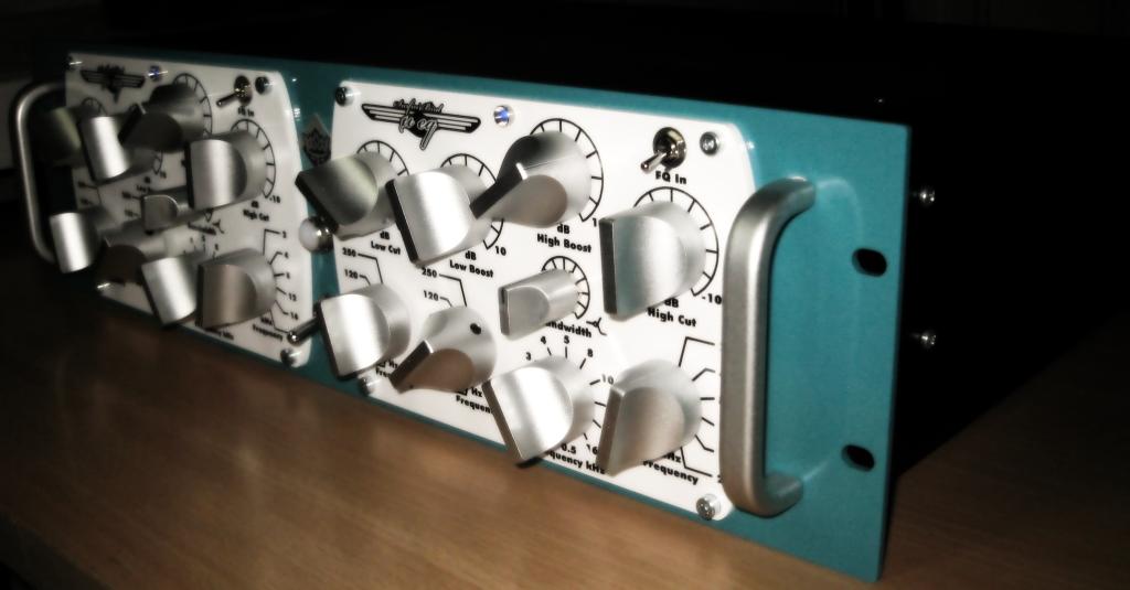
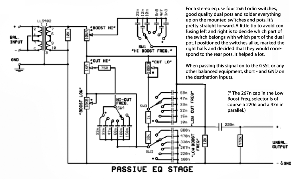
I wanted a passive EQ, but was never happy with the related projects floating around here. None of them had a tube make up stage adequate for my needs.

Design target: Little or no-feedback, no tricks, one fat dual triode per channel. If it doesn't sound good, time to get a new hobby.

I took some passive filter network I found floating around here, and made my own PCB for it, and also created a somewhat generic passive B+ PSU with regulated heaters type PCB. I made my own revision of the g-pultec SRPP stage, but found out that it had inadequate gain for the task. Sound was ok, but with the transformer I chose it was down -5dB from unity. I could always boost gain before the EQ, but then I also found the SRPP stage would start to crap out when pushed. Decent sounding distortion, sure, but not the type I was looking for.

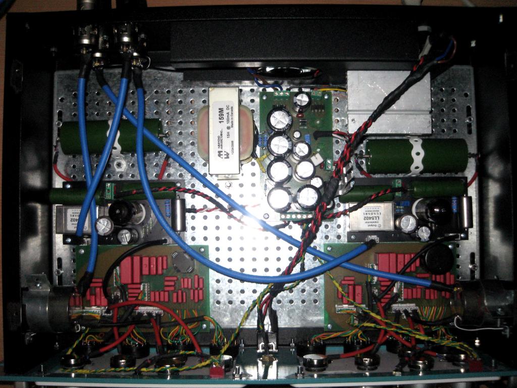
Then I made a reasonably generic PCB for a dual triode tube with two common-cathode stages (no-frills standard implementation) with optional global feedback around them. There's room for LL5402 for the simple reason that I have some of these available for various projects and that they have great price-performance ratio. Many others would work obviously. For this task ECC99 (or its 6N6P russian variant) was a good choice because driving LL5402 (or some similar 2:1 ratio output) and still getting low impedance and low enough distortion is a piece of cake for it. It's true that heater requirements are high, and that the first common-cathode stage now has a bit low gain and far too much drive. But what the heck, lets waste it for good sound. ECC99 is very linear, and that's why I wanted it here. No global feedback necessary with adequately high B+ voltage.

I'm now able to get the "invisible" tube distortion I've always been looking for. No more small-triode 12AX7 shrill distortions for me. I experimented around with the stages (biasing, plate swing, feedback, cathode bypass) quite a bit, and eventually landed a nice combo with about 0.3% THD overall. I could have less, but then what's the point of using this fat linear triode if I can't hear the good stuff. 0.6% THD was already a bit too much warm butter for my taste. Balancing gear for both mastering and tracking duties is a tricky thing to do. Swimming in this type of distortion (around 1% THD) works for all tracking duties thinkable, but only for like one quarter of different types of mixdowns. Maybe next time I'll do some complex relay switch to get two distinct saturation points.

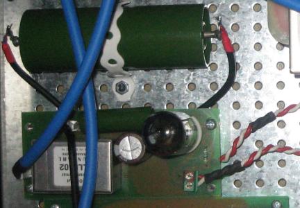
This is the SRPP PCB I had before resorting to redesigning the whole gain stage:
passiveEQ-srpp-test.jpg


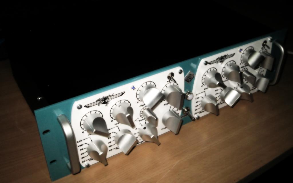
Here's the finished thing with the fat gain stage:
passiveEQ-inside.jpg


passiveEQ-front2.jpg

Let me just say that this is one of the nicest piece of DIY gear I've ever seen. Just beautiful work inside and out!
 
This is an awesome build!

I was checking out the schem and wondering whether using using different switches for the LF boost/cut networks would work as expected and allow you to select different frequencies for boost/cut...

Best,
jonathan
 
Looks cool! Interesting that you can hear a difference between 0,3 and 0,6% distortion.
You must have ears in mint condition, (wish I had) or its even order. Anyways, cool build!
 
ChrioN said:
Looks cool! Interesting that you can hear a difference between 0,3 and 0,6% distortion.

It's not so much the difference between those percentages in general use(measured from RMAA). It's just the fact that one has significantly more headroom than the other (clipping). You will run out of headroom much more audibly. I should also point out that the distribution of harmonics between the cases I tested were different due to feedback.
 
Hi, Kingston !
I'm really pleased to see you ended with such a nice rack !
I'm really interrested in the output schemo as I planned a long time ago to change this part in mine (it has got the Gyraff G-PULTEC output stage)... But days pass and I don't find some time to design a new one and I've got some 6N6P at home so...
Really nice build, mine is still in it's test shape  :-[ .
 
Kingston said:
I will post a quick schematic of the output stage later.

Looking forward to it.  I've been holding off on the same project forever... this is a good kick in the pants.  ;D

Great job. 
 
Here's the line stage.

index.php


Use VR1 and the feedback resistor to get your preference of gain vs. distortion.

But really, there is so little there. It's just taken directly from data sheets. No real design there to be found.

For resistor wattage details, see here: http://www.the12volt.com/ohm/page2.asp

For more information on these very basic building blocks: http://www.aikenamps.com/CommonCathode.htm

[update]

I screwed up with R9. It should be around 400-500 ohm (for some reason I wrote 820). Updated the schematic above. Also wrote in some more common sense.
 

Attachments

  • ecc99-line-stage.png
    ecc99-line-stage.png
    21.4 KB · Views: 1,803
i had the pleasure to visit kingston the other day. his units look even better in real life.


thumbs up!
 
I screwed up with the initial schematic I posted, and now updated it above. I had typo of 820 for the second stage cathode resistor - which would have worked fine - but 400-500 ohms is actually more optimal (which is what I used as well).
 

Latest posts

Back
Top