


Hi everyone,
So, a while ago, after having a particularly unruly singer while I was the FoH guy at a live gig, I thought I'd get up and build a couple more compressors to try and avoid having more "ouch" moments. Being a cheap "just a hobby" guy I decided on trying a PWM approach, cause well, how expensive can a switch be, anyway? Needless to say, that assumption never really holds true, but I still liked the idea, plus there doesn't seem to be a lot of DIY PWM stuff around the forum (I've seen Abe's recreation of the PYE, but not much more), so I went on playing a bit.
Now, I've been lurking on these forums for quite a while and I feel I've learned a bunch of stuff from the people that actually post on here, so I'm going to share my tinkerings so far. I have yet to build an actual compressor, as I've decided to focus on the chopper first, but I think this may be of interest to someone. Feedback, comments and suggestions are welcome; if there is interest I will post schematics and layout once it's done.
So, here is a "snapshot" of my current work in progress on a PWM VCA.
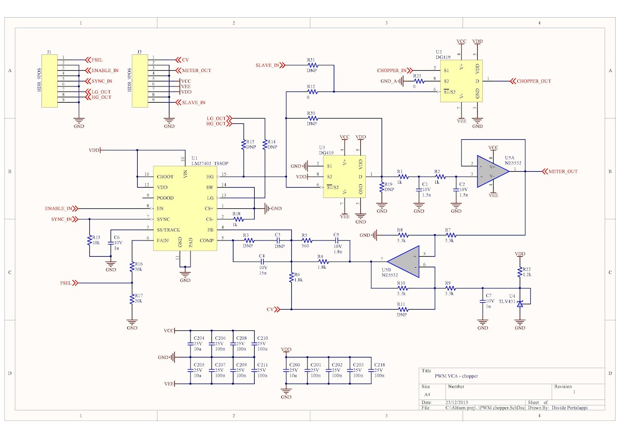
The chopper is built around a LM27402 PWM controller and two DG419 CMOS switches. The way it is set up ensures that there are no "skipped" chopper cycles in heavy GR, and it can be slaved to an external oscillator "sync in" if needed (I don't like the idea of multiple choppers running at similar but slightly off frequencies), otherwise it runs with an internal oscillator; with the values in the schematic, it operates at about 300kHz.
I initially thought about hacking the PWM controller to run open loop by just injecting the CV into the controller's error amplifier, but in the end I just decided to use it closed loop as it seems a more reliable solution. With the values shown in the schematic the loop should have a bandwidth of about 20kHz with no peaking/overshoot.
I'm honestly not sure what the standard way of measuring attack time is, so when I had to decide on the control loop bandwidth I just went with "20k audio bandwidth". However, it is still possible to make it a bit faster.
The gain range is from 0dB to about -26dB. The relationship between CV and gain is linear, which I guess makes this VCA not really friendly for feedforward use. Anyhow, the gain law was supposed to be G = -(CV/5 V), with CV varying from 0 to -5 V, but I made an error in the schematic and the CV range shifted to +2.4/-2.6 V.
The reason for using a second DG419 switch in the feedback loop (U3) in addition to the one used for audio is that the response time of the switch is pretty similar to the minimum pulse width from the PWM controller. I thought this might give a better match between CV and resulting attenuation at high attenuation levels. I also plan to try removing U3 and jumpering R20, to see if it actually gives any benefit.
The "HG out" and "slave in" pins in the schematic are a possible way to make (permanent) stereo pairs: instead of giving the same CV to two boards, one board could have no PWM IC and just be slaved to the other board's chopper signal. If the pair needs to be able to work as independent channels as well, I'm not sure this approach would work as I don't know if the controller floats the HG/LG outputs when disabled.
As for the filters before and after the audio switch, which are connected to the "chopper in" and "chopper out" nets, I took inspiration from http://groupdiy.com/index.php?topic=780, with some added passive filtering right after the switch. Dimensioning of the filter part is not really complete yet, mostly because I was itching for a test board running to make sure the PWM IC behaved as I wanted. I'll post the schematic once I have some values that make sense.
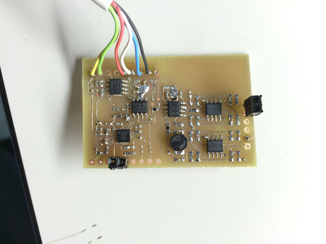
The above is my current home-etchable (but still two layer) version of the layout. I have another version which is a bit more compact but has vias under components, and I'll have a bunch of those made. About component packages, the PWM controller in the photo is a QFN, as TI decided they didn't want to offer samples of the TSSOP version; however, on the final layout I will go with the TSSOP as it's easier. Other components are SOIC, a SOT23 on the bottom layer, and 0805/0603 passives. Personally, I am used to smaller sizes so I consider those to be reasonably easy without any special tools, but I know a lot of people may disagree.
This test board was stuffed mostly according to "whatever is available in the lab that has the closest value to what I need", which is why it's not going to win any linearity prize - there's a power inductor and X7R ceramics in silly small 0402 cases on there. I eventually plan to change those to 0805 NP0s, which should be better, and I'm still unsure whether to stick with the inductor or not.
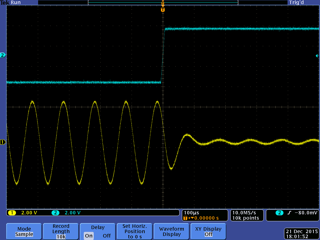
However, I did still take a couple measurements about GR response time. Blue is CV, squarewave from no attenuation to max attenuation, 10us edges; yellow is output.
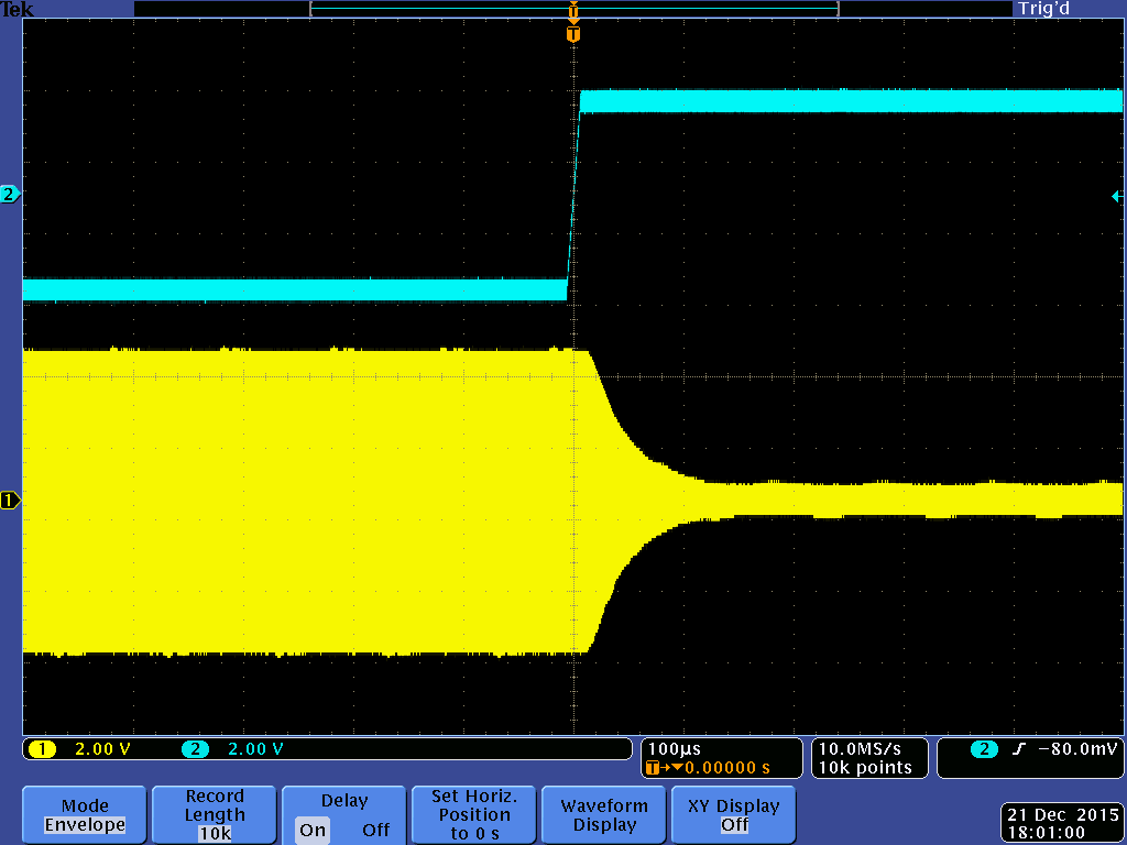
I also took a tentative measure of the modulation residue at the output, even though the current output filters are a bit too aggressive and will need to be modified. Input on this one was a 10V pk-pk, 1kHz sine, chopper was measured running at ~302kHz, and CV set for about 20dB attenuation.
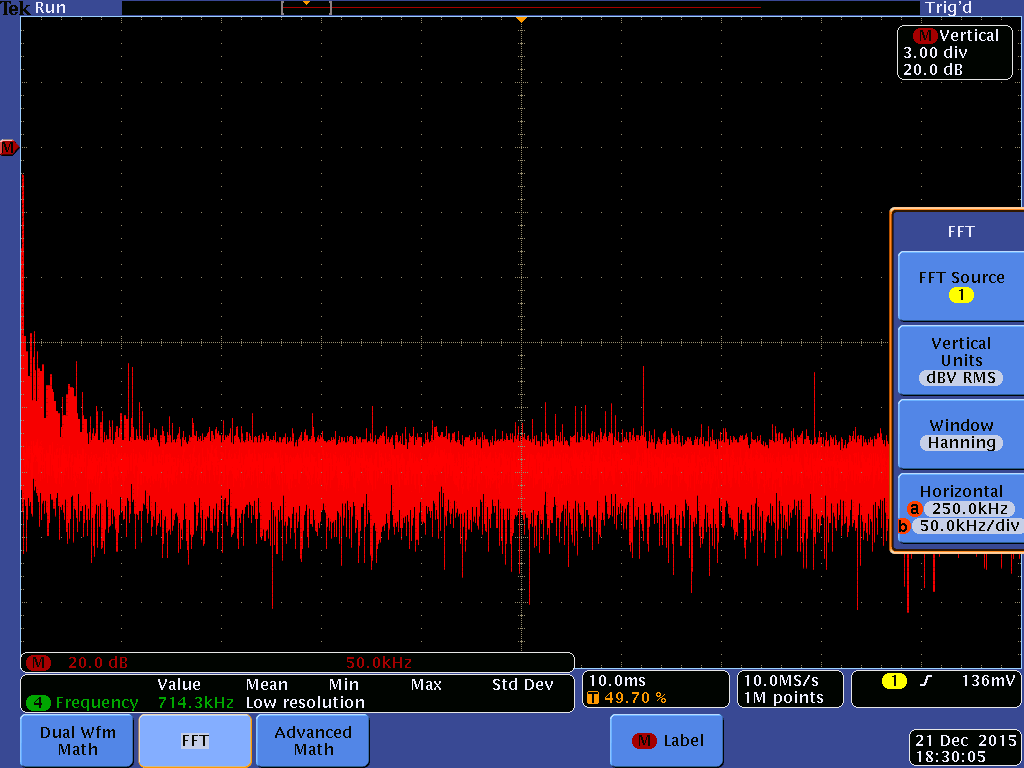
There seems to be something around the 300kHz mark, but it's not quite in the right position, and I'd have expected two peaks, or at least something slightly more symmetrical. But I'll take more meaningful measurements once I fix the filters.
I guess a distortion measurement is of interest as well, but I'm not sure I can perform that with the equipment I have at the lab. I don't have a distortion meter, and if I hook my signal generator it directly to the scope and take a FFT, I can see literally dozens of harmonics some 50-60dB below the fundamental... so either the generator we have is far from spectrally pure, or the scope front end is putting in all that junk.
So yeah, feedback/suggestions/questions etc. on the design are welcome, or if you think there is some measurement I can take that would be interesting to see, feel free to ask.
- Dave
So, a while ago, after having a particularly unruly singer while I was the FoH guy at a live gig, I thought I'd get up and build a couple more compressors to try and avoid having more "ouch" moments. Being a cheap "just a hobby" guy I decided on trying a PWM approach, cause well, how expensive can a switch be, anyway? Needless to say, that assumption never really holds true, but I still liked the idea, plus there doesn't seem to be a lot of DIY PWM stuff around the forum (I've seen Abe's recreation of the PYE, but not much more), so I went on playing a bit.
Now, I've been lurking on these forums for quite a while and I feel I've learned a bunch of stuff from the people that actually post on here, so I'm going to share my tinkerings so far. I have yet to build an actual compressor, as I've decided to focus on the chopper first, but I think this may be of interest to someone. Feedback, comments and suggestions are welcome; if there is interest I will post schematics and layout once it's done.
So, here is a "snapshot" of my current work in progress on a PWM VCA.
The chopper is built around a LM27402 PWM controller and two DG419 CMOS switches. The way it is set up ensures that there are no "skipped" chopper cycles in heavy GR, and it can be slaved to an external oscillator "sync in" if needed (I don't like the idea of multiple choppers running at similar but slightly off frequencies), otherwise it runs with an internal oscillator; with the values in the schematic, it operates at about 300kHz.
I initially thought about hacking the PWM controller to run open loop by just injecting the CV into the controller's error amplifier, but in the end I just decided to use it closed loop as it seems a more reliable solution. With the values shown in the schematic the loop should have a bandwidth of about 20kHz with no peaking/overshoot.
I'm honestly not sure what the standard way of measuring attack time is, so when I had to decide on the control loop bandwidth I just went with "20k audio bandwidth". However, it is still possible to make it a bit faster.
The gain range is from 0dB to about -26dB. The relationship between CV and gain is linear, which I guess makes this VCA not really friendly for feedforward use. Anyhow, the gain law was supposed to be G = -(CV/5 V), with CV varying from 0 to -5 V, but I made an error in the schematic and the CV range shifted to +2.4/-2.6 V.
The reason for using a second DG419 switch in the feedback loop (U3) in addition to the one used for audio is that the response time of the switch is pretty similar to the minimum pulse width from the PWM controller. I thought this might give a better match between CV and resulting attenuation at high attenuation levels. I also plan to try removing U3 and jumpering R20, to see if it actually gives any benefit.
The "HG out" and "slave in" pins in the schematic are a possible way to make (permanent) stereo pairs: instead of giving the same CV to two boards, one board could have no PWM IC and just be slaved to the other board's chopper signal. If the pair needs to be able to work as independent channels as well, I'm not sure this approach would work as I don't know if the controller floats the HG/LG outputs when disabled.
As for the filters before and after the audio switch, which are connected to the "chopper in" and "chopper out" nets, I took inspiration from http://groupdiy.com/index.php?topic=780, with some added passive filtering right after the switch. Dimensioning of the filter part is not really complete yet, mostly because I was itching for a test board running to make sure the PWM IC behaved as I wanted. I'll post the schematic once I have some values that make sense.
The above is my current home-etchable (but still two layer) version of the layout. I have another version which is a bit more compact but has vias under components, and I'll have a bunch of those made. About component packages, the PWM controller in the photo is a QFN, as TI decided they didn't want to offer samples of the TSSOP version; however, on the final layout I will go with the TSSOP as it's easier. Other components are SOIC, a SOT23 on the bottom layer, and 0805/0603 passives. Personally, I am used to smaller sizes so I consider those to be reasonably easy without any special tools, but I know a lot of people may disagree.
This test board was stuffed mostly according to "whatever is available in the lab that has the closest value to what I need", which is why it's not going to win any linearity prize - there's a power inductor and X7R ceramics in silly small 0402 cases on there. I eventually plan to change those to 0805 NP0s, which should be better, and I'm still unsure whether to stick with the inductor or not.
However, I did still take a couple measurements about GR response time. Blue is CV, squarewave from no attenuation to max attenuation, 10us edges; yellow is output.
I also took a tentative measure of the modulation residue at the output, even though the current output filters are a bit too aggressive and will need to be modified. Input on this one was a 10V pk-pk, 1kHz sine, chopper was measured running at ~302kHz, and CV set for about 20dB attenuation.
There seems to be something around the 300kHz mark, but it's not quite in the right position, and I'd have expected two peaks, or at least something slightly more symmetrical. But I'll take more meaningful measurements once I fix the filters.
I guess a distortion measurement is of interest as well, but I'm not sure I can perform that with the equipment I have at the lab. I don't have a distortion meter, and if I hook my signal generator it directly to the scope and take a FFT, I can see literally dozens of harmonics some 50-60dB below the fundamental... so either the generator we have is far from spectrally pure, or the scope front end is putting in all that junk.
So yeah, feedback/suggestions/questions etc. on the design are welcome, or if you think there is some measurement I can take that would be interesting to see, feel free to ask.
- Dave