Access-312 Build Thread

GroupDIY Audio Forum

Help Support GroupDIY Audio Forum:

This site may earn a commission from merchant affiliate links, including eBay, Amazon, and others.
Rellister if input transformer doesnt work while jumpered somethings is not right.
are you saying you are not using jumpers at all??
Did you put a jumper on R6-R7?? and C8 too?? you know waht you are doing?? you are sending signal to ground....!!
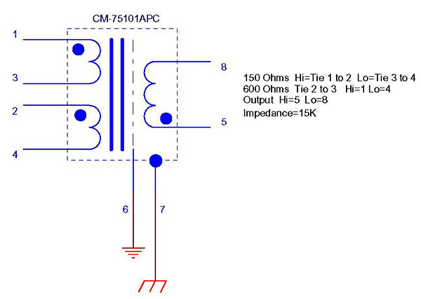
Look at this:
CM-75101APC.jpg
 
the only reason you need to jumper C8 is when installing an 150K resistor on R6-R7.
But given the fact that RC is specific place for that resistor you dont need to jumper R6-R7 or C8.
 
I've got  two of these pres racked up.  Applied power and set the power supply voltage at the opamp sockets on the first one to +-16V.  Then I checked the second pre, but the voltage never stays the same, it drops slowly down past +-15V.  Does this indicate that there is something wrong with this pre?  All the electrolytics and diodes are oriented correctly.

Thanks,
Craig
 
YEah that what happened to me twice..
Im not sure whats going on....i mean happened on this build but not the 2 before with external psu.
 
after loaning my access 312 preamps to a friend now only 3 of 4 channels have phantom power. The power is definitely getting from the PSUniversal to all cards, but then only one seems to be passing the 48v from the card to the XLR pins.. 3 out of the 4 channels are only getting about 1v on each pin. I also just noticed that op amps are being sent +18 and -14v

each channel that is not getting phantom power is only getting about 1volt to input pins 2 and 3.

im annoyed at this, and I have a session on friday where I need these preamps for drums.

he said it literally just stopped working on his royer but it sounds amazing.

I was wondering what could cause this and how I could trouble shoot it.

Thanks regardless
 
wow.
Really impressive builds after one another.
Les tell us how you managed such a nice front panel??
you using GAr2520?
I used 2 channels with gar1731 and 2 with johns burdick SM2520...those are sweet.
 
3nity said:
wow.
Really impressive builds after one another.
Les tell us how you managed such a nice front panel??
you using GAr2520?
I used 2 channels with gar1731 and 2 with johns burdick SM2520...those are sweet.

For the front panel I have found a way to use toner transfer on painted surfaces.

How to make the front panel:
- Paint the front panel. I use standard spray paint.
- Print your design on glossy photo paper for laser printers. It is important that you use a laser printer!
- Position the design (face down) on your front panel. You may want to fasten it with some tape to make sure it won't smudge.
- Iron the back of the paper to make it stick to the panel. For the first minute, just press down, don't move the iron to much. The reason for this is to prevent the design to smudge. Use the tip of the iron to make sure you get the paper to stick really good. The total ironing time should be around 6 minutes. The heat setting is the key here, for my iron it's set on "silk". If it gets to warm, the paint will be ruined.
- When you are done ironing, put the whole thing in warm water. I use running water. After some seconds, change the temperature to where your hands won't get burned when touching the panel. (If the paper releases itself at this point, you didn't get the ironing right)
- Carefully tear off the paper. You should only be able to tear off the back side of the paper. Use your finger (NO nails) to get the rest of the paper off. Be careful! I sometimes use a brush to remove any leftovers.
- Use clear matt paint to seal it off. This is for concealing the cloudy effects you get from the paper burned into the paint. Glossy won't work.

You may need to do it several times to get it just right, but you should be able to get great an professional looking results for as little money as possible. And it is truely DIY.


For your other question:
Yes, it is GAR2520. I may try something else for the next one. (Have to make 5 microphones and 2 compressors first, to get my studio up and running for the recording of my first album)

Pål N.
 
Late to this thread.  Friend/client was building these and ended up with some crappy pots.  I found some replacements...See:

http://www.mouser.com/ProductDetail/Alpha-Taiwan/RV16AF-10-15K-C10K-3/?qs=EusSljnoWfijrk04lOg5wg%3d%3d

Bri
 
Okay,

Replaced toriod
Replaced power supply
Replaced caps and resistors in phantom power circuit

when powered on:
all +/- 16 volt rails get to the op amps
+48 volts works on all channels but not on channel one unless I wiggle the input transformer the right way

I figured the problem was just the input transformer (I already tried re seating it). So I plugged in a 58 and it worked wonderfully. I plan to replace the input transformer.

Then I tested with a u47 to see how it sounded. With the u47 plugged in, I get a loud buzz (and yes it's far away from any high powered tube stuff). Then I tried a different mic that uses phantom power. It seems to get the buzz with any kind of mic that is not a standard moving coil microphone. But 58's and 57's work.

Where do I think things are getting wacky? I think with the non moving coil mics, ground is getting in the signal. There are two ground paths here.. one is a 0v path coming from the PSU that go's to each board. The other ground is the chassis ground that hits the IEC inlet ground and on all XLR's pin one. I currently have these two grounds running separate. The power supply seems to burn up diodes when they are connected.

Any idea what could be going on? I think I'm finally close. Please help! I'm so frustrated.. If you give me advice that works I'll give you a free GAR 2520.. I bought a few extras to test and see if its the op amps.. I'm pretty sure its not the op amps.

Edit* sorry for being an idiot.

 
buildafriend said:
schematic
all 1/4 watt resistors
R1, R2, R11 6.8K
C5 22uf 63V
the schematic and parts/values question was related to the psu.

You do the math, why your 'all 1/4 watt resistors' might not have been the best descision. [P=U2/R] when you fill in 48 for U and 6800 for R.
C5 with 22uF/63V might be a typo (suggested value was 220uF/63V), but ripple filter one decade up now at 15.4Hz would still be effective.
(hint: scroll some posts back for some BOM edits)
 

Latest posts

Back
Top