[ACMP investiupgradifications] All things PREAMP

GroupDIY Audio Forum

Help Support GroupDIY Audio Forum:

This site may earn a commission from merchant affiliate links, including eBay, Amazon, and others.
Dave from Altran sent me their normal shielded inductor package. Trying to attach it here.  It has up to 8 taps for different inductances,  but it is mechanically different, so it won't fit perfectly. I will email for pricing and to see if there are any other packages available, even unshielded, that could maybe fit better. 

Am I to understand that the Carnhill fits the PCB without modification or did you wire it in?
 

Attachments

  • TAPPED INDUCTOR PACKAGE.pdf
    19.5 KB
On the pinout - depends on where you decide 'pin 1' will be.

I labelled 'Pin 1' to be the first connected pin and counted from there.

The Carnhill part does not drop-in replace the stock inductor, physically.
It is electrically compatible. Indeed, I think it will be closer to spec'd frequencies.

I have it wired with wires. See pic earlier in thread.
The OEP can will fit the board but it is strictly a DIY affair. Hack the can
lid, put leads to the inductor, insulate inductor and mount in can  etc

Messy, but around 50aud in cost (ie. relatively cheap - an aud is not worth s**t these days)
Cheaper than buying mu-metal sheet for me.
 
Can someone recommend a part compatable replacement for the Mid Hi inductor for the 73? I dont have the equipment to measure the ones I have to find a replacement.
Thanks
 
alexc said:
On the pinout - depends on where you decide 'pin 1' will be.

I labelled 'Pin 1' to be the first connected pin and counted from there.

The ceramic form has the pins labeled 1 to 8 - that's what I was going by. And it is important if you're going to get drop-in replacements, as the pin spacings are different. You'll notice they are in two groups of 4 with equal spacings, but wider spacing between the end pins of the two groups.
 
BTW, here's my hack for this.

inductor.jpg


inductor_clamp.jpg


ACMP81_done.jpg


Not elegant, but it works.
 
> The ceramic form has the pins labeled 1 to 8 - that's what I was going by.
> And it is important if you're going to get drop-in replacements, as the pin spacings are different.
> You'll notice they are in two groups of 4 with equal spacings, but wider spacing between the end pins of the two groups.

True enough.

When I measured it, I found the resistance (and assume inductance) increases as I have shown.
I wired it that way and it works as expected.

However I could be wrong - I'll check again and post back.

Thanks
 
I'm not saying you're wrong - you're right that the pins can be numbered starting anywhere. I just wanted to be sure you realized there is a much wider spacing (in your numbering scheme) between pins 1 and 2, than between 2-3, 3-4, and 4-5, which is not clear from your drawing. This would be important if manufacturing or buying a replacement to drop into the board.

Thanks Alex for all your work on the 81 - it's been very helpful. (You wouldn't know of any schematics for the 73, would you?)
 
Thanks Crazydoc - I too have followed your work with great interest.
Your input has been very much appreciated.

I like your shielding solutions, particularly on the toroid. The double layer
with cardboard spacer is really good! And the fact it has shown results
makes me hopeful.

Truly, I haven't done much - just discovering the same as you and others!

On the pinout, I just want to make sure I have it as I think.

On the schematic, the inductor entry point is marked as '1' and progresses to '5' with
inductance increasing as you go. So I think I wanted to be consistent with the schematic

- but this does not match the part pin numbering and also crosses the 'pin grouping divide'
  as you noted.

Sorry - I don't have the schematics for the ACMP73 or the ACMP84.
 
it's worth noting those curious tabs around the pwr xfmr ,

doc did you first try an L shape around the xfmr then the full circle

And Roddabod can confirm i first mentioned twisting the xfmr long ago ,
if only that were enough , he makes a good point that even if you can't hear
the oscilations from the Xisters can still be there
 
First off:
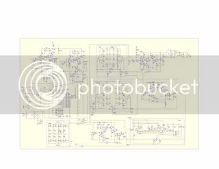
http://goose-tracks.com/thegeekgoose/images/scem73wv9fi2.png

Its in Chineese and doesnt have the metering or power sections on it.  Ive asked for the 2nd page which should have that on it but Ive never receieved a response at any rate, its the only one I know of. (I posted it quite a few pages back BTW)

Now a couple of more pics:
midhieqacmp73.jpg


Note the way the inductors are laid out. As if they could be 2 physical parts. We know thats not the case in these units cause theres only 1 inductor on this board. This confused me a little why I was having a hard time finding a part compatable replacement.  I went back to the source and found this:

1073midhieq.jpg

In the original, they were 2 parts. Sowter has them. I might try replacing the 1 inductor with the 2.
 
I can email the 73  [ chinese as recieved somewhere in this thread


scem73gd2.jpg


thanks for the good energy so far everyone


edit by clintrubber on Gregs request

thanks it was almost freezing my computer as an attachment , i can email it
to anyone who can't find it  , gboboski at shaw.ca
 
Finally got my stuff. Had arrived months ago at some family who just came to visit! Got 2 mics and 2 84s.

I tested one 84 to see what was going on with it, it had hum and buzz at first, so I played with the toroid a bit (ended up flipping and rotating), now the hum is gone, and the buzz is only there when I engage the mid band (I thought it was audible when engaging the low band as well at first, so this is an improvement I guess). Anyway, it is highest at .36, a bit less at .7, just audible at 1.6K and I think it's there at 3.2K but not sure... maybe I'm hearing things. It is more audible with the high-Q button depressed in all cases, and disappears when this frequency selector switch is set to OFF.

The low band is not inductor based, so maybe it was hum I was hearing in that band. Anyway, curiously enough, the low and high pass filters are inductor based, but they do not cause any buzz.

I wonder if a new inductor would help in mid-band case. Will try to find some copper foil and try shielding this one first.

Also want to add that the gain switch pop is still there when the pre is set to line-in, just much less of a pop.

I'll try to get to testing the second unit later.. 
 
The impedance selector , maybe only because of the lower gain  / ratio
makes a difference too the pushed in setting will give less Hum
i don't think it is humbucking or anything like that .
twisting the pxr xfmr made no difference on mine but maybe i'll try
flipping it , did you do that with the wire attached ?
 
Didn't try the impedance switch... oops. didn't even think of it cuz it's on the back.  Anyway, I did all this with the thing turned on, listening to the hum/buzz through headphones and trying to find the sweet spot. Here is a crappy pic I took with my laptops built-in camera, since I haven't seen any 84 pics yet.  I wonder why the other inductors don't cause problems.. Just the distance? 

Let me know if flipping helps.
 

Attachments

  • Photo 10.jpg
    Photo 10.jpg
    116.1 KB
I opened up my only ACMP73 today to check it out. Here's the first thing I saw:

ACMP73_buss-connector.jpg


When my shipment arrived in December, I had an 81 that wouldn't pass signal, and this was what I found:

ACMP81before.jpg


That's 2 of the 3 I've opened so far (one 81 to go.) Mighty impressive assembly quality and QC on these.


The 73 at least doesn't have the eq oscillation, as the circuits are different. There is some 120Hz hum with eq switch engaged, which is improved, but not eliminated, by rotating the toroid. Both inductors have hum when engaged, especially the mid-low on 0.36 with boost. This is considerably improved with inductor shielding, so I think that shielding the toroid and the inductors is going to make this serviceable.

Noise/hash is equivalent to the 81 at high mic gain, and of course the ever-present gain switch pop is there in full force.
 
crazydoc said:
Mighty impressive assembly quality and QC on these.

This is Mr. Lee speaking, the factory replesentative of the Chinese crone-fab.

Prease accept our sincele aporogies, but it ain't neccesaliry a QC ol assembly issue.

How about just poor cheap components & lude postmen thlowing alound in wild fashion with these boxes ?

Fol that leason we don't accept any lesponsibirity, have a good weekend, thank you  ;)

  Mr. Lee
 
i ve build a two channel 1084 with carnhill inductors. and i ve got inductor oscillations (50hz) on the ba182c board (the hight pass filter). i ve tried shielding the power traffo the inductor , add L alu piece of sheet to separate the psu from the boards etc...with no real good succes.
only remove the psu cure the trouble.(btw the other ba182c inductor don t oscillate and is 20cm away from the psu traffo.(even the ba194 with a t1280 just above the 182board don t oscillate))
so now i have to do an external psu box.....
this to say that even a carnhill inductor can t solve all oscillations troubles induced by a power psu traffo.(i ve tried several one thoroid or not..)
i now know that there a good reason ams neve and others don t put their psu within the same rack as the EQ...
ps i ve tried my 1081 in the studio (only the transistors mod and mic "pop" resistor change (thanks 0dbfs)and a 620 ohm output resistor termination on a switch.
As found on the oscillo ,i don t have buzz on the eq. 'at least at usuable level for mixdown) 50hz here.
i hope i can soon compare the diy 84 and the tnc81 eqs ....
audioforge
 
I wonder what kind of effect moving the inductors as far to the front-left by pigtailing the inductors.
And drill a new hole to move the mains transformer to the far right-back.
 
tarnationsauce said:
I wonder what kind of effect moving the inductors as far to the front-left by pigtailing the inductors.
And drill a new hole to move the mains transformer to the far right-back.
I don't think moving the toroid a few inches will make any difference - the first thing I did was I move it over the edge (as far as the wires would allow) and it made little difference.

I extended the low-mid inductor with about 3 feet of wire well outside the box, (see post# 354 this thread) and the wire picked up so much EMI it was even worse. Maybe if the wires were shielded... (which is what I did for the 3" or so I used to move the inductor the way I did, though for that short distance it didn't make any differece if the shield were grounded or not.)
 
Back
Top