You are using an out of date browser. It may not display this or other websites correctly.
You should upgrade or use an alternative browser.
You should upgrade or use an alternative browser.
[ACMP investiupgradifications] All things PREAMP
- Thread starter clintrubber
- Start date


Help Support GroupDIY Audio Forum:
This site may earn a commission from merchant affiliate
links, including eBay, Amazon, and others.
Hi Steve,
You didn't manage to get the specs for the 6L2 inductor in the '84, did you? Just saves me the hassle of pulling it out.
If it helps, I can provide response curves if you'd like them. Thing is, I was looking for copies of original reponses of either the '73 and '84 channels, and nobody responded, so they aren't really much use as yet. I think you'll find that none of the frequency bands are dead-on in reality. The bands are also relatively wide.
Cheers,
Roddy

crazydoc
Well-known member
Very similar. Thanks for posting those. What does it look like with "Hi Q" out?
Here's a similar sweep that alexc posted a while back, but on the 81 at 1.5kHz. Only 8dB of boost at max (excluding 20 to 30Hz.)
http://home.att.net/~crazydoc/ACMP/alexc-freq-sweep-81.jpg
Here's a similar sweep that alexc posted a while back, but on the 81 at 1.5kHz. Only 8dB of boost at max (excluding 20 to 30Hz.)
http://home.att.net/~crazydoc/ACMP/alexc-freq-sweep-81.jpg
crazydoc said:Very similar. Thanks for posting those. What does it look like with "Hi Q" out?
Quite similar again. It's not radical the Hi-Q switch. It did cross my mind making it really tight for hard notches, but since it does sound nice, i'll probably leave it.
Alex's curve does look wide, but at low boost, Q is wide.
See if you could replicate this:


![Soldering Iron Kit, 120W LED Digital Advanced Solder Iron Soldering Gun kit, 110V Welding Tools, Smart Temperature Control [356℉-932℉], Extra 5pcs Tips, Auto Sleep, Temp Calibration, Orange](https://m.media-amazon.com/images/I/51sFKu9SdeL._SL500_.jpg)


crazydoc
Well-known member
rodabod said:See if you could replicate this:
You'll have to explain their meaning to me. The bottom graph seems to represent phase shift/distortion, but what that means in realtime audio I have no clue (though I assume straight horizontal lines in each graph would be desirable, preferably at zero dB or degrees.)
crazydoc said:rodabod said:See if you could replicate this:
You'll have to explain their meaning to me. The bottom graph seems to represent phase shift/distortion, but what that means in realtime audio I have no clue (though I assume straight horizontal lines in each graph would be desirable, preferably at zero dB or degrees.)
The first graph (I hope) is just a frequency response graph for a -6dB cut @ 700Hz. The phase response graph shows us how the phase is shifted in degrees by the eq. This is partly what gives the eq its sound character and is why analogue eq's can often be preferable over digital as they have a noticeable "sound". On the other hand, we can design linear-phase eq's by using digital techniques which should in theory be more transparent.
A case of major phase shift in a sort-of eq is your typical 2-way loudspeaker cross-over. Often the tweeter will be wired out of phase with the woofer since during the cross-over frequency the phase shift will be such that the lows will be out off phase with the highs coming from the crossover.
crazydoc
Well-known member
How do you generate a phase response graph?
crazydoc said:How do you generate a phase response graph?
Well, these days you'd hope it could simply be done "automatically" by hardware or software. We don't really need that here though. I was more interested in the response curves for starters.
Steve Hogan
Well-known member
crazydoc said:You'll have to explain their meaning to me. The bottom graph seems to represent phase shift/distortion, but what that means in realtime audio I have no clue (though I assume straight horizontal lines in each graph would be desirable, preferably at zero dB or degrees.)
Any real circuit or filter (one made from resistors, capacitors, or inductors) has a phase response that changes in exact correspondence to the change in magnitude. This is absolutely predictable and repeatable due to the fact that the magnitude of a real filter is changed by the interaction of resistors, (which do not shift audio signals in time) and the reactive capacitors and inductors which have a 90 degree phase shift. The phase graph shows how a steady state signal is displaced in time as it passes through a filter or other circuit. Digital filters can change magnitude only (without affecting phase) by doing math on the instantaneous levels and changing the numbers to make the magnitude bigger or smaller. In real filters the action of capacitors and inductors cause 90 degree phase shifts of the signal compared to resistors.
Unfortunately, Roddy's phase graph is in need of calibration in terms of the numbers, but the general shape is discernable. During that portion of a frequency response curve which has flat magnitude, the phase plot will be at zero degrees and flat as well. When the magnitude response begins to roll off, then the phase response will move negative degrees and when the magnitude response staightens out again (or zero's) the phase curve will again go straight. When the magnitude response goes up, the phase response will go positive. This is completely predictable because the magnitude response is changed by the time (phase) shifts between the components that bend the curve.
To play with this, download a free copy of LT Spice from the www.linear.com website. You can use this easy-to-use spice simulator to play with various passive filters and trace their magnitude and phase plots easily. You can even plug in the ACMP (Neve) values and predict within a hundredth of a dB exactly what is going on.
Although computer simulating the phase response of a filter is easy in Spice, making phase measurements is very difficult due to the need to very accurately determine where zero degrees (no time displacement) really is. Roddy's phase graph appears to me to be in need of calibration in that respect. It also is being affected by the phase response of his converters, I think, or there is a really severe HF rolloff on the DUT.
Phase basically describes the difference in time of any given frequency between that frequency entering the circuit and the time it leaves the circuit expressed in degrees of a sine wave of that same frequency.
One must be very careful to think about phase correctly when it come to describing its effect on audio waveforms.
Let's consider an audio waveform passing through a device in which all frequencies are delayed exactly the same amount of time. The shape of the waveform would be undistorted because no frequencies would be delayed more than any other frequency and therefore all the spectral components that make up that waveform would arrive at the proper time to make the waveform exactly the same before the device and after the device. The waveform shape stays the same, it just comes out of the device a bit later than it went in. The time delay can be nanoseconds or weeks -- but as long as all frequencies are delayed exactly the same amount, the waveform remains undistorted.
If I choose a frequency-independent delay time that is, let's say, equal to 1 degree of a 1 kHz signal, that same amount of delay would represent 2 degrees of a 2 kHz signal, 10 degrees at 10kHz, 20 degrees at 20 kHz and 40 degrees at 40 kHz, etc, etc. Such a frequency-independent delay would have Linear Phase. If we want to know how any audio device affects the shape of the audio waveform in a meaningful way, one must mathematically remove the phase degrees that are the result of frequency-independent delay and then plot deviation from linear phase. Deviation from linear phase is the graph that matters, for example, when evaluating audio tranformers. The traditional "phase" response at 20 kHz made by observation on an oscilloscope is meaningless without removing the frequency independent delay first.
Steve Hogan
Well-known member
rodabod said:You didn't manage to get the specs for the 6L2 inductor in the '84, did you? Just saves me the hassle of pulling it out.
These are measurements of only one sample, so there was no averaging to help find the typical values:
ACMP-84
Sample: Connections: L (mH) R (Ohm) Q Nominal Frequency:
6L2 Pin 1-2 51.6 40.3 7.66 18 kHz
6L2 Pin 1-3 74.7 49.0 9.05 14 kHz
6L2 Pin 1-4 95.86 56.2 10.08 10 kHz
6L2 Pin 1-5 139.27 68.9 11.86 8 kHz
6L2 Pin 1-6 181.74 79.3 13.28 6 kHz
Pin 1 is common on this inductor.
FWIW, The L/C filters on these ACMP preamps are actually passive and are just buffered by the amplifiers on the cards.
This is why the Q's are so low -- they are made to shape the "big picture" response, not notch out problems.
crazydoc
Well-known member
I don't understand this. Does this mean, if you split a signal (say a 1kHz sine wave) into two parts of equal magnitude, put one part through resistor R, and the other through resistor 2R, and then sum the signals, they will be out of phase, since they now differ in magnitude?Steve Hogan said:Any real circuit or filter (one made from resistors, capacitors, or inductors) has a phase response that changes in exact correspondence to the change in magnitude.
Steve Hogan
Well-known member
crazydoc said:I don't understand this. Does this mean, if you split a signal (say a 1kHz sine wave) into two parts of equal magnitude, put one part through resistor R, and the other through resistor 2R, and then sum the signals, they will be out of phase, since they now differ in magnitude?Steve Hogan said:Any real circuit or filter (one made from resistors, capacitors, or inductors) has a phase response that changes in exact correspondence to the change in magnitude.
I'm not sure I understand the question, but in the case of resistive voltage dividers, pads, etc. there are no frequency dependent components, just resistors which pass all frequencies equally. All frequencies are attenuated equally, not just one, so the phase vs frequency graph is a straight line at zero degrees. When I wrote "Any real circuit or filter..." perhaps I should have written "Any real filter ..." In other words, a filter circuit that treats some frequencies differently than others -- Either to boost or attenuate. In the real world this takes frequency dependent components like capacitors and/or inductors, which do have phase characteristics that go along with the magnitude changes they produce. After re-reading your question I wonder if you are connecting/confusing phase with absolute polarity. That's one of the reasons it's a bad idea to label a polarity reversal switch "phase".
It took my attending my first formal electronics class for me to catch on to the fact that Ohms law doesn't work with capacitive and inductive reactance.
Chapter 1, pages 29-42 of The Art of Electronics, by Horowitz and Hill, has a good explanation of all of this sort of stuff. They spent a lot more time writing that chapter than I did composing my couple of paragraphs. Their explanations are very good and easy to understand, and if you don't have this book, I highly recommend it. Horowitz and Hill should be on the bookshelf (if not in the bathroom) of every audio DIY addict. I refer to it at least 3 times a week. My copy is in tatters.
crazydoc
Well-known member
Thanks for trying to explain it to me Steve - I'm sure you have better things to do. I wanted to confirm that purely resistive components have no effect on phase, as I had always believed. I guess it was the wording "Any real circuit or filter (one made from resistors, capacitors, or inductors)" where I inferred "resistors (or) capacitors or inductors" that confused me.
I'd always thought that phase was a function of frequency, inductance and capacitance, but not magnitude -I'll need to wrap my mind around that. But I guess, in my simple way of thinking, if you charge a capacitor with a higher voltage, it will charge faster, thus affecting its reactance for a given frequency, and thus the phase of a signal passing through it.
Anyway, thanks for the explanations, but please don't waste any more of your time on them. I've found this online text that I'll try to peruse - it seems pretty straightforward:
http://www.allaboutcircuits.com/
Steve Hogan
Well-known member
ACMP Gain Switch Mods -- Line-In first:
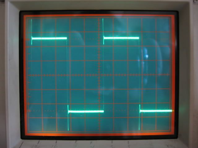
The ACMP preamps all share the same basic input circuitry. The Line input transformer is a 4:1 stepdown transformer supplied by the Chinese with the same load that Neve used to terminate their Line In transformer: 2K2 in parallel with a 2.2nF cap. When I first saw the cap directly across the secondary of the transformer in the schematic, I was suspicious that I would encounter severe overshoot from the transformer due to the capacitive load resonating the transformer. As the square waves below show, I was correct.
Step-down line-input transformers will usually terminate best with just a resistive load. This transformer is no exception. It has excellent square wave response when terminated in just the resistive portion of the ACMP load. With the 2K2 load resistor in parallel with the 3 dB per step Line attenuator, the Line input transformer sees a load ranging from 656 Ohms to 709 Ohms, depending on the gain setting of a '73 or '84.
The "Line In" attenuator network in the ACMP-81, on the other hand, has an extra 510 Ohm resistor (1R68) in series with the stepped attenuator which causes the load on the transformer to vary from 872 Ohms to 912 Ohms depending on the position of the gain control. I'm not sure why the extra loss is put into the '81, but it can be adjusted by changing the value of 1R68.
So here are the pics:
1 kHz ACMP-81 Line Input Transformer Secondary with 900 Ohm Load in Parallel with 2.2nF cap (as delivered).
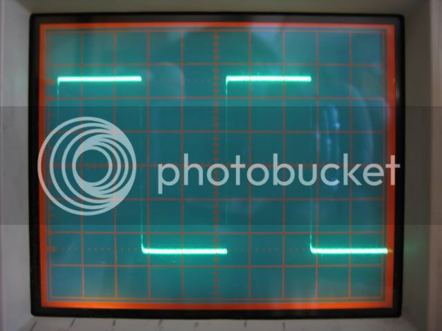
1 kHz ACMP-81 Line Input Transformer Secondary with 900 Ohm Load only, 2.2nF cap removed.

10 kHz ACMP-81 Line Input Transformer Secondary with 900 Ohm Load in Parallel with 2.2nF cap (as delivered).
10 kHz ACMP-81 Line Input Transformer Secondary with 900 Ohm Load only, 2.2nF cap removed.
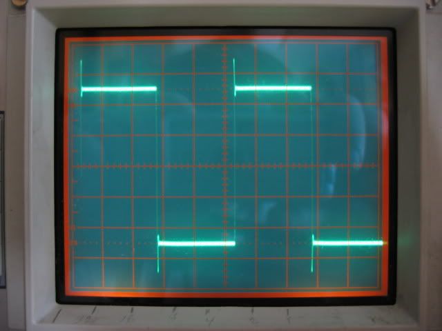
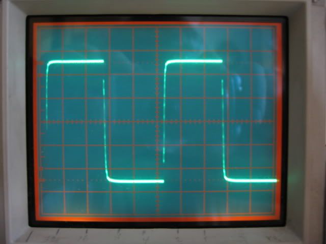
1 kHz ACMP-73/84 Line Input Transformer Secondary with 700 Ohm Load in Parallel with 2.2nF cap (as delivered).

1 kHz ACMP-73/84 Line Input Transformer Secondary with 700 Ohm Load only, 2.2nF cap removed.

10 kHz ACMP-73/84 Line Input Transformer Secondary with 700 Ohm Load in Parallel with 2.2nF cap (as delivered).
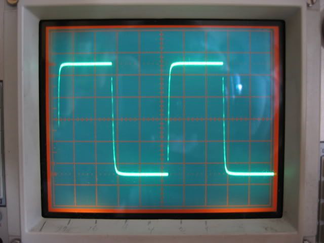
10 kHz ACMP-73/84 Line Input Transformer Secondary with 700 Ohm Load only, 2.2nF cap removed.
So what do the square wave photos tell us? The line input transformer will be far less harsh and have a much clearer midrange if the overshoot is eliminated. I would recommend pulling out the 2.2nF cap (C2 in a '73 or '84; 1C21 in an '81) in a heartbeat.
In addition to determining that the 2.2nF cap is a bad idea, I also derived a revised set of 1% values for the Line input attenuator resistors that take the maximum error relative to 3 dB gain steps from 0.25 dB to less than 0.03 dB (calculated). There will be additional variations due to the 1% resistor tolerance which will degrade that a little bit, but with the revised values it will still be much more accurate than the original values. The 0.25 dB improvement is modest, however, so changing the resistors is optional with the exception of the 39 Ohm resistor in the '81 which is afflicted by the wrinkly bad coating syndrome and should be replaced along with any other resistors showing signs of deteriorated blue coating. In the revised set of values, only the 200 Ohm resistor stays, and the rest are changed. If one doesn't trust the original resistors, there is no problem swapping them out -- it takes mostly time, because the resistors are relatively cheap.
Next is the Mic Transformer analysis, and the rework of that attenuator network to eliminate the pop and spread the gain steps out among 10 working positions and an "OFF" instead of 11 working positions. This one's a lot harder to figure out than the line in.
The ACMP preamps all share the same basic input circuitry. The Line input transformer is a 4:1 stepdown transformer supplied by the Chinese with the same load that Neve used to terminate their Line In transformer: 2K2 in parallel with a 2.2nF cap. When I first saw the cap directly across the secondary of the transformer in the schematic, I was suspicious that I would encounter severe overshoot from the transformer due to the capacitive load resonating the transformer. As the square waves below show, I was correct.
Step-down line-input transformers will usually terminate best with just a resistive load. This transformer is no exception. It has excellent square wave response when terminated in just the resistive portion of the ACMP load. With the 2K2 load resistor in parallel with the 3 dB per step Line attenuator, the Line input transformer sees a load ranging from 656 Ohms to 709 Ohms, depending on the gain setting of a '73 or '84.
The "Line In" attenuator network in the ACMP-81, on the other hand, has an extra 510 Ohm resistor (1R68) in series with the stepped attenuator which causes the load on the transformer to vary from 872 Ohms to 912 Ohms depending on the position of the gain control. I'm not sure why the extra loss is put into the '81, but it can be adjusted by changing the value of 1R68.
So here are the pics:
1 kHz ACMP-81 Line Input Transformer Secondary with 900 Ohm Load in Parallel with 2.2nF cap (as delivered).
1 kHz ACMP-81 Line Input Transformer Secondary with 900 Ohm Load only, 2.2nF cap removed.
10 kHz ACMP-81 Line Input Transformer Secondary with 900 Ohm Load in Parallel with 2.2nF cap (as delivered).
10 kHz ACMP-81 Line Input Transformer Secondary with 900 Ohm Load only, 2.2nF cap removed.
1 kHz ACMP-73/84 Line Input Transformer Secondary with 700 Ohm Load in Parallel with 2.2nF cap (as delivered).
1 kHz ACMP-73/84 Line Input Transformer Secondary with 700 Ohm Load only, 2.2nF cap removed.
10 kHz ACMP-73/84 Line Input Transformer Secondary with 700 Ohm Load in Parallel with 2.2nF cap (as delivered).
10 kHz ACMP-73/84 Line Input Transformer Secondary with 700 Ohm Load only, 2.2nF cap removed.
So what do the square wave photos tell us? The line input transformer will be far less harsh and have a much clearer midrange if the overshoot is eliminated. I would recommend pulling out the 2.2nF cap (C2 in a '73 or '84; 1C21 in an '81) in a heartbeat.
In addition to determining that the 2.2nF cap is a bad idea, I also derived a revised set of 1% values for the Line input attenuator resistors that take the maximum error relative to 3 dB gain steps from 0.25 dB to less than 0.03 dB (calculated). There will be additional variations due to the 1% resistor tolerance which will degrade that a little bit, but with the revised values it will still be much more accurate than the original values. The 0.25 dB improvement is modest, however, so changing the resistors is optional with the exception of the 39 Ohm resistor in the '81 which is afflicted by the wrinkly bad coating syndrome and should be replaced along with any other resistors showing signs of deteriorated blue coating. In the revised set of values, only the 200 Ohm resistor stays, and the rest are changed. If one doesn't trust the original resistors, there is no problem swapping them out -- it takes mostly time, because the resistors are relatively cheap.
Next is the Mic Transformer analysis, and the rework of that attenuator network to eliminate the pop and spread the gain steps out among 10 working positions and an "OFF" instead of 11 working positions. This one's a lot harder to figure out than the line in.
Hi Steve, I found exactly the same results for the line input transformer. I've also done the same for the mic in (more tricky) and the line out.
You can get the characteristics "good" but ideally I was aiming to get closer to the Carnhill sound which has something slightly different going on in the low-end (in this circuit) from what I can see.
Just a thought; are you happy publishing all this information which the Chinese/US distributors will blatantly steal for future designs?
Roddy
maxwall
Well-known member
- Joined
- Nov 17, 2004
- Messages
- 1,141
Steve,
You mentioned in a earlier post 'allocation of power trasnformers' , Is there a formal list for ordering one
of these power transformers. Or is the first run of 40 to be followed by many more ?
Also, with regards to phase changes due to magnitude and other influences, How do these changes manifest themselves
audibly to the listening experience. I'm trying to connect the technical explanation with real world listening results.
Is this like flipping the phase reversal switch on a console channel strip where you can hear a change or is it much different ?
It would be nice to train the ear to recognize bad phasing , but this seems difficult.
Steve Hogan
Well-known member
electrochronic said:Steve,
You mentioned in a earlier post 'allocation of power trasnformers' , Is there a formal list for ordering one
of these power transformers. Or is the first run of 40 to be followed by many more ?
Also, with regards to phase changes due to magnitude and other influences, How do these changes manifest themselves
audibly to the listening experience. I'm trying to connect the technical explanation with real world listening results.
Is this like flipping the phase reversal switch on a console channel strip where you can hear a change or is it much different ?
It would be nice to train the ear to recognize bad phasing , but this seems difficult.
Re Transformer availability:
At the present time I have been notified by prospective purchasers an interest in approximately 50 transformers, almost equally divided between 73/84 types and '81 types.
I plan to do another production run, but only after the first 40 are sold. After the amount of hours I have spent figuring all this out (hundreds more than I first anticipated), I am hoping to modify as many units and/or sell as many kits as possible. My cash flow will not permit me to make more transformers until I have sold the first 40. Those who are having me do the installation of their tranformers and other mods will have first crack at the first 40 pcs, and those who want kits will be processed on a first come first served basis. Some clients have sent deposits on kits, and they will get first divs on the kits. Approximately 20 pcs are already spoken for with deposits. Refer to my contact info below if you want to reserve a kit or send your unit in for modification on this first batch of tranformers.
Re Phase changes from filters:
Until the invention of digital audio with digital filters that could change magnitude without a corresponding change in phase, all equalizer circuits changed the phase in a way that corresponds to the magnitude (frequency response) changes. We have generally come to hear these phase changes as a normal part of how an EQ changes the audio. This is NOT the same as Polarity reversal (unfortunately labeled "phase" on some devices) which reverses the absolute polarity of the audio signal. As I and others have discussed in depth elsewhere, reversal of absolute polarity is clearly audible due to the fact that real music is not made from sine waves, but often very asymmetrical waveforms, which sound wrong when the absolute polarity is reversed.
Steve Hogan
Well-known member
rodabod said:Hi Steve, I found exactly the same results for the line input transformer. I've also done the same for the mic in (more tricky) and the line out.
You can get the characteristics "good" but ideally I was aiming to get closer to the Carnhill sound which has something slightly different going on in the low-end (in this circuit) from what I can see.
Just a thought; are you happy publishing all this information which the Chinese/US distributors will blatantly steal for future designs?
Roddy
To be honest, I was thrilled that the Line input transformer could be made to behave properly by simply removing the unfortunate parallel capacitor which resonated with the leakage inductance in the transformer to cause such a nasty overshoot. I now consider the HF response on the cap-less line input transformer to be excellent.
This morning I isolated the mic input transformers and made exact measurements of their DCRs, their turns ratio, etc. This is a bit tricky because one must remove the 12K load resistor, the 1.2nF cap, and lift a resistor on the gain switch and turn the switch to the lifted position to free the secondary from all circuit loads. The phantom feed resistors had to be removed as well, but they are going to be replaced anyway. I did a preliminary look at the square wave response, and it had a nasty overshoot similar to the line in transformer with the factory supplied components, especially in the 2:1 (low gain) position. It looks like the square wave overshoot and ringing can be fixed just like the line input transformer, but it will likely require an RC network in addition to the resistive load provided by the gain switch and the rest of the circuitry.
I have spent many hours modeling the amplifiers in LTSpice to determine their actual input impedance in order to correctly adjust the Gain switch resistor values. The shunt leg of the switched attenuator is bridged by the input impedances of the preamps, and the input impedances are surprisingly low. The first stage input Z is only 3700 Ohms, and the second stage input Z is only 4938 Ohms in "Mic" and 8700 Ohms in "Line". This means that all the gain resistors in the switched pads must be "fudged" to account for how the lower portion of the voltage divider is changed by being loaded by the preamp.
The circuit as delivered, loads the mic transformer differently when it is feeding the first stage compared to when it feeds the second stage. This has the unfortunate effect of changing the frequency response of the transformer slightly and changing the loading on the microphone. Because the load on the secondary is reflected to the primary of the transformer, the Input Z of the mic preamp, with the as-delivered factory gain switch values, is lower when the gain switch is set to higher gains than when it switched to lower gains. This is quite independent of the change to the Input Z which occurs when the mic transformer primaries are switched from series to parallel with the rear panel switch. Although the gain increases when the primaries are paralleled, (1:4 step up instead of 1:2) not all the gain is realized because the input impedance becomes much lower at the same time, so the microphone is loaded down more.
Since I must rework the resistor values in the gain switch anyway, I am considering changing them in a way that keeps the load on the transformer the same, so the Mic input Z of the preamp will stay the same at all front panel gain positions. You should see the Excel spreadsheet that I use to figure all that out at the same time.
My game plan is to change the nominal 11 postions gain switch with 6 dB nominal steps, to 10 positions with 6.6 dB steps and an "off" position in the middle that prevents the pop.
Regarding the Chinese figuring out what I am doing and doing it themselves? Even when given a schematic, the Chinese and others seem to not get it right, mainly because they have no idea why the circuit is the way it is. We batted that all around a while back in this forum and I figure that ship has sailed. Those that buy the kits will be paying $25 for the instruction booklet that contributes (a little) for my hours of figuring this all out. I am open to advice on ways to protect my intellectual property investment, but I believe that the better folks understand what is going on inside their gear, the better they can use it, so I tend to be pretty free with information. In that way I probably take after my mentor Deane Jensen. After all is said and done, we are striving to make tools that produce great music.
Similar threads
- Replies
- 11
- Views
- 540