Active Design Using Inverters?

GroupDIY Audio Forum

Help Support GroupDIY Audio Forum:

This site may earn a commission from merchant affiliate links, including eBay, Amazon, and others.

skrasms

Well-known member
Joined
Jun 16, 2004
Messages
72
Location
Gary/Purdue-Lafayette
This has come up in a couple circuits I've seen, and I'm really curious about the “how” part of it. It seems that logic inverters can be used in place of opamps in lo-fi designs. For example, the inverter in this circuit:
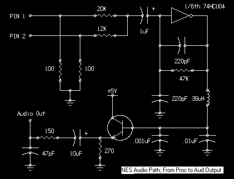
NESAudio.gif


The signals from pins 1 and 2 are audio signals, leading to the 7404 circuit to do summation and filtering. I imagine the inverter is behaving like an opamp with a grounded V+ terminal and negative feedback. How well does this actually work?
 
You need unbuffered inverters for this (see also the 'U' in the inv.-type-number), and then the effective internal circuitry comes down to just a NMOS & PMOS (say 'FETs'), as below.

The external 47k resistor 'tames' the appetite of this construction to slam its output to the pos or neg supply rail (a.k.a. it gives it a usable operating point for amplification, and linearizes the raw inverter steepness), resulting in.... an amplifier.

4.48.png


The input-resistors and the 47k feedback-R are just like with a 'normal' opamp: inverting config., virtual earth, gain for each signal given by the R-ratio.


Bye,

Peter
 
[quote author="dale116dot7"]But it's not a particularly good virtual-earth amplifier. It works, but pretty much any op-amp will outperform this amplifier in pretty much every measureable way.[/quote]

Fully agreed, there's 'functionalty' and 'performance'.

I first saw these in the Craig Anderton 'hot tubes' overdrive circuit, that later made it into some MXR and/or EH design. The first use of inverters for linear gain will have predated that.
 
[quote author="bcarso"]I have a funny story about using "high-voltage" CMOS (like the 4XXX series) for ~linear amplifiers that I will tell someday if you are all good.[/quote]
Please?

Pretty please?

Pretty please with a cherry on top?

JD 'and sugar' B.
 
[quote author="bcarso"]I have a funny story about using "high-voltage" CMOS (like the 4XXX series) for ~linear amplifiers that I will tell someday if you are all good.[/quote]

Yes, let's have it :cool:
 
> logic inverters can be used in place of opamps in lo-fi designs

ALL "logic" gates ARE linear amplifiers, just specced and used at 9,999% THD.

Specific simple CMOS inverters can be bodged into a fairly linear mode. I thought RCA published this but now it has Fairchild's logo:

http://www.fairchildsemi.com/an/AN/AN-88.pdf

FWIW: you can bugger RTL into a linear mode, but you probably don't want to admit you know what RTL is. TTL too, though for some reason I've honestly forgot, it is difficult. (I think the output stage conducts both sides, worse than CMOS, and melts.)

Totally off-topic, but perhaps of interest:
http://www.national.com/an/AN/AN-1515.pdf
A Comprehensive Study of the Howland Current Pump
Robert A. Pease January 29, 2008
 
The first time I saw the AN-88 note it was in the 1977 National Semi CMOS databook, dated July 1973 with the author listed as Gene Taajes. Further on in the book Mike Watts contributed AN-118, CMOS Oscillators.

I worked for Watts when he was the President of Harman Interactive. He basically persuaded Sidney Harman and Co. to get into computer/multimedia audio, and presided over the first couple pieces of business, with DEC and Compaq.

According to Mike, he wrote some still earlier material for National on using CMOS in the linear mode.

This is background for the story, which I will get to someday---don't have time to write it now.
 
You know you've only given us an appetizer..

You should do it in installments if it's going to take a while..

Story hour with Brad! It'll be a Brewery hit!

:green:
 
I really hate to do this because it is so much resembling the setup of how I got impatient, and came to tangle with a fine man (analag) in here in the early days, when he seemed to just be teasing us.

But I really am swamped right now, and a good story deserves a bit of effort to have it come out right and true.
 
I recall this being discussed decades ago. One problem to watch out for is the current draw/dissipation when operated linearly and both devices are conducting. This becomes more of an issue when operated near the upper limits of CMOS rail voltage.

This strikes as one of those curiosities without much practical utility. Perhaps if you want to gimmick a GP opamp to drive rail to rail this in series with the opamp output would get you there simpler than building up a pair of common emitter devices, but you still have the dissipation issues if output is operated near mid supply. For a low drive current application you could add current limit resistors to + and - rail of CMOS, so you'd then be able to drive to rail but with the series impedance.

What ever... yes a simple inverting gain stage, but much happier operated with outputs saturated high or low.

JR
 
Indeed John, I wouldn't recommend it with anything other than 4XXX series gates, unless a unbuffered higher-speed one is operated at very low voltage. In fact I've done just that to make crystal oscillators running off a single alkaline cell using the 74LVU04, IIRC.
 
http://www.uoguelph.ca/~antoon/tutorial/xtor/xtor10/xtor10.html

yo, heres' some howto :cool:


but, you need to know that UBE CMOS invertors are MADE TO ROCK. In other words, not to behave politely. :green:
 
[quote author="bcarso"]In fact I've done just that to make crystal oscillators[/quote]
FWIW, you know that that doesn't make Mr. Vittoz too happy, but it'll get the job done and well enough in most cases nevertheless.... but not the most optimal circuit, if one was given to do it otherwise.


'The Mother of all crystal oscillator articles' (imo):

E. Vittoz, M. Degrauwe and S. Bitz, “High-performance crystal oscillator circuits: theory and applications”, IEEE Journal of Solid-State Circuits, vol. SC-23, pp. 774-783, June 1988.
 
[quote author="clintrubber"][quote author="bcarso"]In fact I've done just that to make crystal oscillators[/quote]
FWIW, you know that that doesn't make Mr. Vittoz too happy, but it'll get the job done and well enough in most cases nevertheless.... but not the most optimal circuit, if one was given to do it otherwise.


'The Mother of all crystal oscillator articles' (imo):

E. Vittoz, M. Degrauwe and S. Bitz, “High-performance crystal oscillator circuits: theory and applications”, IEEE Journal of Solid-State Circuits, vol. SC-23, pp. 774-783, June 1988.[/quote]

In this case the design objectives were operating down to low voltages, moderate frequency stability, and reliable starting behavior---the application was a minature 76.8kHz transmitter for running on a snake inside of a plastic pipe, used in conjunction with a VCXO PLL-based receiver.
 
[quote author="clintrubber"]E. Vittoz, M. Degrauwe and S. Bitz, “High-performance crystal oscillator circuits: theory and applications”, IEEE Journal of Solid-State Circuits, vol. SC-23, pp. 774-783, June 1988.[/quote]
Thanks for the recommendation, and especially timely seeing I still have a few days of free IEEE access left :wink:

Jim Williams of LTC has written an appnote which shows several logic gate-based crystal oscillators (and proceeds to point out that You Shouldn't Do That, while giving examples of better XO configs). Well worth a read.

JDB.
 
It's interesting that Williams shows a 3904 in a preferred circuit.

I found that a 2.4576 MHz VCXO using a 3904 was quite vendor-sensitive; some parts (I think they were Samsung) didn't work at all. A two-transistor stage, with a PNP emitter follower driving the 3904, was much more robust.
 
[quote author="jdbakker"][quote author="clintrubber"]E. Vittoz, M. Degrauwe and S. Bitz, “High-performance crystal oscillator circuits: theory and applications”, IEEE Journal of Solid-State Circuits, vol. SC-23, pp. 774-783, June 1988.[/quote]
Thanks for the recommendation, and especially timely seeing I still have a few days of free IEEE access left :wink:[/quote]

Nice, my pleasure. It may be of somewhat lesser use since it's not using off the shelf parts (a.k.a.: external Xtal but the rest is part of a dedicated integrated circuit), but the wisdom crammed into the pages of that article remains impressive :wink:

Cool A'Note you linked.

Bye,

Peter
 
Back
Top