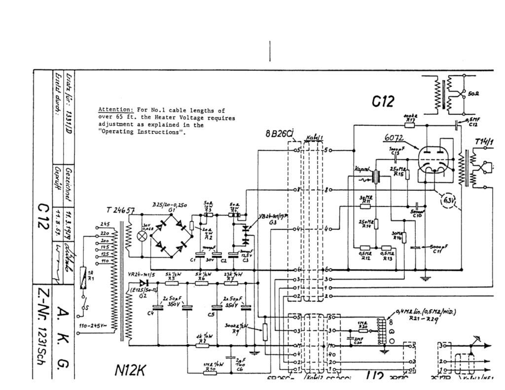
AKG Ela M251 with AC701 Neuman M49 circuits

GroupDIY Audio Forum

Help Support GroupDIY Audio Forum:

This site may earn a commission from merchant affiliate links, including eBay, Amazon, and others.

gary o

Well-known member
Joined
Dec 28, 2004
Messages
1,532
Location
uk
AKG Ela M251 with AC701 B+ voltage does anyone know what it should be ......Is it 120 VDC as with the 6072 version........I have made a point to point version of the circuit but using a CV465 instead of a AC701 As I read a 5840 is similar to AC701 & CV465 is interchangable with 5840....the mic sounds great at 120V B+ but am wondering if a little too high.....

Thanks for reading...
 
I think 120vdc is where you wanna be.  I am in the process of getting stuff together to mod a apex 460 into an elam251 and I have to upgrade the ziners in the PS to 60vdc each to give me 120vdc output so I think this is right.

-Scott
 
Thanks Scott  are you doing the 6072 circuit tho ....I know that should be 120VDC I have a point to point version of the 6072 circuit that most people go for....but this circuit is with a CV465 mini tube wondering if is the same B+ its similar tube used in the Dorsey circuit that only has 90-100V B+...... well it work nice sounds very similar to the 6072 circuit...

thanks once again I will watch with interest your 460 to 251 conversion....all the best.
 
Thanks Gary,
What mic did you use to build your 251?

I have a few schematics and what not, just have to figure out how to fully read them. 

I have all of the tube options written down as well as the transformers and capsules. 

Just have to look at the prices and add everything up.

I am going to go with the plate follower as an original 251 is that.

Just curious as to what caps and resistor brands did you used.  What brand names are in the 251?

I wanna try to be very authentic with this build and build it as close to a 251 as I can.  all the same guts.

-Scott


hi Scott here are some experiments

http://www.groupdiy.com/index.php?topic=48212.0

Didnt use a mic my electronics are in a pencil tin didnt bother copying exact component brands, tho I use best quality I can find, I think its a little pointless if you dont have original capsule/basket & transformer, Im lucky to have a real T14/1 from the sixties but no original capsule & in my humble experience the capsule makes by far the biggest difference in sound....if you read my other thread youl see I tried many variations of electronics & tho a little different they all have same capsule sound but thats just what i found so far its great fun experimenting I think.....
 
I've only found the schematic with 6072a and 110 V B+. Never seen a E version schematic, but the N52 PSU for AC701 equipped mic's seem to put out 120 V.

That said, B+ doesn't mean much by it self. Anode and cathode resistor determine the bias, gain and output impedance at the given B+, and all these affect each other. The B+ affects the ways to achieve right polarization voltages too.

5840 (pentode) is not similar to AC701 (triode) but wired as triode can be use as a substitute in some circuits. But that depends of the circuit (B+, Ra, Rc, transformer). Don't know about CV465 but it seems to be at least close to 5840.

It really helps if you learn to play with plate curves, somebody here thought me how to but can't find the thread. How I do it: choose B+ and value for Ra, draw a load line, choose a bias point and calculate the value for Rc. Draw a tangent for the grid line at the chosen bias point. Now you can calculate the output impedance and the transformer ratio needed. Then choose an other B+, other Rp and other bias point. Keep playing (it's fun and you learn).

You can choose many points that'll work, signal from the capsule is unlikely to overdrive the tube. But if I understand correctly too hot bias (high idle current) can make a mic noisy.

I'm a musician and mic freak, not even close to an EE, so don't buy all I wrote without studying yourself, there might be some misconceptions there.
 
Old thread I know but I have been re visiting my experiments & having been wondering about a M49 circuit http://www.tab-funkenwerk.com/id89.html & comparing it to the AKG circuit I read they could use the same transformer , Im wondering which is the better circuit ..... sadly dont have a AC701 so was going to use the 5840 perhaps ..... can anyone shed any light on the these circuits also I only wantto use one side of RK47 or Tim Cambell capsule ..... can I omitt any components ..... thanks
 
Hi Gary,

Referring to Oliver's M49 circuit and the 251E, they are both cathode biased and, aside from the different heater voltages, really only differ significantly in the value of the output cap, which varies substantially between the various ELAM models.

T14/1 may have different inductance from BV11a. Oliver's 1uF would seem to be a good starting point for your T14/1, but it might pay you to experiment with this once you have finished the mic, as you are a singer and the desired effect will be highly subjective.

You can omit C1 and R2, C4 and R8 in Oliver's circuit as they are only needed to polarise the rear diaphragm and couple it into the amp.
 
Thanks Dan I already have a little point to point version of the C12 AC701 circuit (but with 5840 tube)& I have a out of work capsule sitting here a cheapy RK47 was wondering what to use it for so thought of the m49 as I already have a MK47 with nice capsule & a Ela 250 ish with 6072 circuit & tim cambell capsule, wanted another flavour , I keep forgetting the mic sound is mostly the capsule so it will be another flavour so maybe I needn't worry too much about the electronics, it does seem that most folks here dont like to change the tried & trusted recipes C12 U47 M49 & so on, me included it feels wrong to have a 47 ish capsule with a C12 ish circuit but why not I have some old mic input trans I will reverse & try I may build the M49 circuit too for fun & experiments.

Am I right in saying these circuits are all meant to be flat amps U47 C12 M49 & others and thererfore should all sound the same really regardless of design & transformer

In my humble non scientific experiments they sound pretty much the same so far... BUT flat designed solid state circuits sound dull, not as lively in comparison, not that I dont like the sound but.....
so if they all supposed to be flat how do they sound different.....

thanks
 
Gary,

It's true that the circuits you've mentioned are all essentially flat in terms of frequency response - ie they have none of the frequency-shaped negative feedback that you find in the U67 and basically just pass the signal from the capsule to the transformer unaltered (leaving aside the normal bandwidth limits set by the grid resistor and cap-coupled transformer output stage).

If you take away the resistors and caps that are there to filter the power and bias the active components, the fundamental components of any tube mic circuit - capsule, tube, transformer - basically just need to work together well, in terms of impedance matching the signal from the capsule to the outside world. After that, the subjective consideration of desirable sound comes into play with regard to the quality of the components and the colouration they impart in combination with one another. In DIY, this can only be found through trial and error.

The capsule does have the most impact on defining the sound, and the fundamental difference in these capsules can be defined by whether the diaphragms are edge-terminated or centre-terminated.

The scheme used to bias the tube makes a subtle difference to the character of the circuit that, once you are familiar with it, helps make the sound of a particular microphone recognisable as falling into one or the other of the categories:


C12: edge-terminated capsule, *fixed-bias;
251: edge-terminated capsule, cathode-biased;
U47: centre-terminated capsule, fixed-bias;
M49c: centre-terminated capsule, cathode-biased.


So you see, all bases are already covered. You are not exactly breaking any rules by putting a 47-type capsule in a C12-ish circuit at all - it's then close enough to a U47 in terms of topology, just not a clone.

There is a lot of fetishism around here, which is why there is so much attachment to the 'authentic' iterations of the classic mics. That, and the eagerness by some to exploit the ready market for clone kits.

Your mic will have it's own sound anyway, as you are using different components to begin with. I say go for it!  :)


[EDIT: * corrected below]
 
MagnetoSound said:
C12: edge-terminated capsule, fixed-bias;
The C12 is actually cathode biased but the cathode resistor is in the PSU just to keep you on your toes.  8)  I haven't got a link to a C12 PSU convenient  :(

It was probably done to keep the large cathode decoupling cap out of the mike ... or it may be that they wanted a fixed bias version but never got round to it.
 
ricardo, it had me fooled for a while ... mostly because I had been using C28s for most of my working life and I had just assumed it was the same circuit. :)

But the 1k at R8 means that the bottom of the HT secondary is held negative wrt ground and bias is applied to the grid from this point.


AKGC12schem_zps67bc07cd.jpg


Thanks Dan & others for helping me to understand these circuits, most interesting..... so the Ela M251 with the AC701 is a lso cathode biased & although a flat amp sounds different to a C12 due to tube...

I have some C28As here too I hear they have a better noise spec than the C12 tho similar but not the same circuit ( I think the B+ goes throught the OP tran) I think it may have been Dan again helped me with info on the C28 circuit, shouldnt we be using the C28 circuit rather than the C12 for DIY.....I did try my favorite capsule on a C28A & compared it to same capsule in my MK47 & my Ela251 type circuit ( its kinda a TB1 circuit with higher value grid resistor for full fat sound) the C28 had a lot more level but thinner sound I guess due to the 8Meg grid resistor

Maybe I could DIY a C28A circuit but beef up the grid resistor to my taste or maybe the C12 as I say I have the ElaM251 with 5840 tube on my bench sounds great but sounds same as my Ela ish circuit with the 6072  so may try C28a for different flavor ....
 
MagnetoSound said:
But the 1k at R8 means that the bottom of the HT secondary is held negative wrt ground and bias is applied to the grid from this point.
AKGC12schem_zps67bc07cd.jpg
As ALL the valve current flows through 1k R8, the DC conditions are EXACTLY as if there was a 1k cathode resistor.

That means the circuit has all the advantages of cathode bias.  eg less susceptible to valve variations & aging compared to 'real' fixed bias.

All they've done is to take a standard cathode bias circuit (with 1k cathode resistor) and transfer "earth" to the cathode.  No problem as long as nothing else takes power from the same supply.
 
ricardo said:
As ALL the valve current flows through 1k R8, the DC conditions are EXACTLY as if there was a 1k cathode resistor.


Doh! What else could be causing the drop? ::)  Now that you put it that way I can see you are exactly right - although I think the term 'cathode bias' is difficult to apply here: the tube is effectively self-biased of course, as the drop through R8 is proportional to the plate current.

As you say, it looks very much as if they intended a real fixed bias circuit to follow on.

How interesting! Thanks for clarifying.

 
to most engineers, the less parts the better, (cheaper pleases the boss, more dependable, easy to keep the stock room bins full,) so if you see a million parts in a mic circuit as opposed to fewer parts, you can almost be certain that they were having trouble getting the sound right,

a circuit that performs a simple function yet has a million parts is known as a "kludge"
these are the circuits you want to avoid if possible, there are some very "kludgey" looking Neumann and AKG circuits out there, for sure,

so if you see a simple circuit, chances are it is a good design from the get go, the capsule matches the mic body, which matches the grill, which matches the circuit which matches the transformer, look at the U47 circuit, not much there, just the bare minimum to get the job done, they may have lucked out with the initial design as it is quite the classic, so if you have to pick a circuit...

here is an informative link on U47 transformers just FYI:

http://www.andreas-grosser.com/2009/10/a-description-of-all-transformers-in-u47-article-by-ag/
 
CJ said:
to most engineers, the less parts the better, (cheaper pleases the boss, more dependable, easy to keep the stock room bins full,) so if you see a million parts in a mic circuit as opposed to fewer parts, you can almost be certain that they were having trouble getting the sound right

Implying they may have started out with fixed bias, then changed it prior to release?

Perhaps - a few resistors would likely have cost less than the redesign needed to make it 'normal' cathode bias ...

 
MagnetoSound said:
Implying they may have started out with fixed bias, then changed it prior to release?
I think this is very unlikely.

While Clem Beaumont, my mike mentor at Calrec was still around, I could have confirmed this as he was a personal friend of Bernhard Wiengartner who did the C12 for AKG.  I can tell you BW hated using AC701 and thought the 6072 a far better tube.

You have to remember, engineering decisions are often made for very mundane reasons.

My guess is they couldn't get the decoupling electrolytic they wanted inside the mike tube.  It was a good decision as "self-bias" is far less finicky than fixed bias.

The Soundfield Mk4 has a single supply cos I ran out of pins on the connector.
 

Latest posts

Back
Top