All things Green Pre

GroupDIY Audio Forum

Help Support GroupDIY Audio Forum:

This site may earn a commission from merchant affiliate links, including eBay, Amazon, and others.
Try & isolate where the noise is coming from. So do a listening test on the outputs of all the opamps & see what stage is causing the noise.

Make sure the DC voltages on the opamps & transistors are the same between the good & bad channels.

Peter
 
Peter, i did checked my voltages...and at pin 1 ac no1 ic i have +3.84....instead of -3 something???
is that BC 550 replacement?? 2N4401???
 
Tried to think seeing the schematic but i'm not that experienced with electronics so could this be the Diodes??
 
We have discussed the diodes. Are they good or not? Pull them, see if it helps. If not pull something else & replace it, try the transistors. Please dont come to me with questions like "I'm using a sub, mybe the pins are different" Aaaaargh.

I'm ratty this morning & I dont give a shit.

You have to be proactive & try things.
 
I'm ratty this morning & I dont give a shit.

Hah hah,

Oom that made my day... I feel for you, now run along and get some coffee and sue the builder (personal joke).

But in defense of Pete (not that he needs it) it is impossible to go and find the BC subs and do all the leg work to find out if they are compatible or not!!! This DIY not DIFY (Do It For You).

This really is a 'simple' DIY project and if you take your time, are careful, and triple check your work odds are on power up you will have a solid, working pre. I have built around 10 channels I think and only twice did I have small error, one was a bad cap which I traced in a matter of minutes, the other a broken track on an etched board.

All the tools and knowledge you need for this project are here at your disposal.

Tried to think seeing the schematic but I'm not that experienced with electronics so could this be the Diodes??

LEARN to read the schematics, if you want to grow in DIY this is a good place to start.

3nity, no offense man, but spend some time learning more about the 'how and why' and less on the 'do'.

I've been reading your errors on the Greens for a month or more now and recently saw your thread about the none working Animal Pres as well.

It seems you are rushing ahead and not taking the time to learn to understand the circuits, or at least the components and how to troubleshoot along the way.

All the best, and please take this as encouragement, not criticism.

The best advice I got in DIY was from PRR when I started almost 2 years ago... 'Any monkey can build a car... but not everyone can fix one'.

Cheers

Matt
 
Hey 3Nity,

Sorry man I was just kidding as I thought you were no need for the :mad: face as I put a :green: face after my comment, this is all suppossed to be fun :thumb:

Cheers

Matt
 
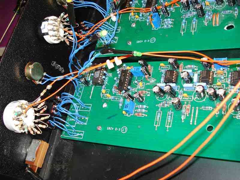
So I've had a completed 4 channel green pre for a while... No problems since the first time it was powered up. I love them!

On one channel, my green and yellow LED's will not turn off. I've tried going through the steps on the 100K trim pot but it doesn't seem to make a difference.

The rest of this channel is fine.. it matches the other 3. Should I replace the trim pot or is there something else I should look into?

-richie

thanks in advance :grin:
 
ok I checked the DC voltages of the 339 against a channel that was working.. on a lot of pins the voltages were under what the working channel had.

if it was -14Vdc the bad one would have -10 .. or much less / same thing with the positive Vdc's

The rest of the IC's are getting matched voltages.

I swapped the chips to make sure it wasn't the chip and the LED's still didn't work in the same channel so its not the chips.

I'm not really sure how to trouble shoot this since the preamp works perfectly still.

-richie
 
I forgot to say that the red LED is not on, the other three are

DSC01977.jpg


-richie
 
Sounds like a plan.

I'll take a pic and label voltages tomorrow on it. I would hope it's not a wrong resistor value considering the fact that they were up and running for a couple of months now... perfectly. Also, I used Ptown's kits, which made it impossible to mess up. I really don't even care about the LED's that much its just that a lot of this circuit is for the LED's and I don't want them to go to waste.

Thanks for the direction Peter.

-richie
 
I have a question about the 47uF caps. Three are specifiied as 63v.

Am I correct in thinking these are the 63v caps?

63v_caps.jpg


Looking at PeterC's stuffed board, one appears larger than the others? (The one with yellow arrow in picture below.)

Should this one be 100v or greater?

larger_value.jpg


I'm assuming the remaining 47uF's are all OK at 25v regardless of the silkscreen footprints. But if there is an advantage to using larger voltages, please let me know. I'd like to use larger values if it will give more robust performance / longer life - unless larger values mean greater dialectric absorbtion and more phase shift. (Always a tradeoff.)

Thank you for anyone with thoughts on the subject.
And thank you Peter for making this project possible.

kato
 
Back
Top