You are using an out of date browser. It may not display this or other websites correctly.
You should upgrade or use an alternative browser.
You should upgrade or use an alternative browser.
All things Green Pre
- Thread starter HappyTom
- Start date
Help Support GroupDIY Audio Forum:
This site may earn a commission from merchant affiliate
links, including eBay, Amazon, and others.
Phrazemaster
Well-known member
Phrazemaster
Well-known member
peterc
Well-known member
Sweet!
Phrazemaster
Well-known member
Thank-you kind sir!
Phrazemaster
Well-known member
Hey, I'm really excited to report that my torroid keeps in all it's magic smoke! Apparently my first test hurdle is a success! My lighted switch lights, the torroid stays cool, and reads about 17.75v on each rail no load. Guess my wiring is OK after all, for the mains and IEC and fuse!!
Thank-you folks for all the tremendous support; I'll keep reporting my experiences here and hopefully it will be helpful or amusing to some.
Thx!
Mike
Thank-you folks for all the tremendous support; I'll keep reporting my experiences here and hopefully it will be helpful or amusing to some.
Thx!
Mike
Phrazemaster
Well-known member
Just wanted to mention something about the connections.
Originally I had some awesome, beautiful crimp connections, but I just wasn't feeling right about using crimps for mains.
So I redid them (took a LONG TIME), using some uninsulated crimp connectors which I then soldered to the wires, then coated with an insulating rubber made especially for wiring.
When I finally put it all back together, the voltages for the torroid only read 18.16v per rail, as opposed to the 17.75v I was getting before.
OK, maybe there's just a fluctuation in the mains 110v which is affecting the output (I don't know if this would affect it or not), or perhaps the extra .41v is due to having better connections since now it's soldered?
Anyone have a thought?
Thanks,
Mike
Phrazemaster
Well-known member
PSU Issues
Hi, after hooking everything up, all voltages actually look about right. However...
I thought I would check how many mA was coming from the phantom, so I hooked up my dmm and it was about 11 or 12mA; seemed fine. After a minute or two I noticed the mA began to drop, and continued to drop. Then I noticed the phantom regulator was REALLY HOT!!! I have a huge heatsink on it, and I started smelling...stuff.
What is strange is that the 317 for the phantom does not get hot at all unless I connect it to the ammeter section of my fluke dmm. Am I doing something really stupid, or do I just need to replace this lm317?
I am posting an image with all my voltages in dark blue next to the right voltages. Also, the bridge rectifier reads -23.9,and +23.9 on its +/- legs. Voltages from the torroid legs are 17.9vAC as measured directly on the PSU traces.
Thanks; the project is a blast and I could really use your help.
Attachments
peterc
Well-known member
Remember, you have to measure current in SERIES. Break the supply line & insert the meter to read current.
Is this what you did?
Peter
Is this what you did?
Peter
Phrazemaster
Well-known member
No Peter, I R an IDIOT when it comes to this...I knew there was something I was probably doing wrong...I actually connected the leads directly to the fluke--guess I coulda fried the fluke, but it seems fine.
I remember vaguely this rule back in high school physics.
So do you think I'll need to replace the lm317 since it got so hot?
I'll try again...thx for being so supportive.
I remember vaguely this rule back in high school physics.
So do you think I'll need to replace the lm317 since it got so hot?
I'll try again...thx for being so supportive.
Phrazemaster
Well-known member
Geez you'd be within your rights to ignore this question, but I don't quite understand...how would I do this? Would I have to connect a microphone, or a resistor, across the phantom rail first and then break it? What I had done was take the 48v lead and connect that to the fluke + lead, and then ground to the fluke - lead.
Would this be breaking the circuit?
Would this be breaking the circuit?
Phrazemaster
Well-known member
OK, yes, I know google is my friend...
So I think this explains why the lm317 got so hot...it was in short circuit to ground basically...
"Why is it a very bad idea to connect an ammeter directly across a voltage source?
Due to the ammeter's very low resistance, it will "draw" a lot of current from the voltage source. In effect, the ammeter will form a short circuit with the voltage source, potentially damaging the meter and/or the source. In applications where the voltage source possesses very little internal resistance of its own, the current surge resulting from such a short-circuit may be huge. Very large surges of electric current are capable of heating wires to the point where their insulation bursts into flames, as well as causing super-heated blasts of plasma (electrically ionized gas) to form at any point of electrical contact where there is a spark. Either of these high-temperature conditions are hazardous to the person holding the meter and test leads!"
I am testing the voltage on the phantom rail and it is still rock-solid at 48.4vDC; do you think I need to replace the lm317 that got so hot? This is my first project like this and I'm just trying to get it right. I still don't know how to test the current on the phantom rail; I think I would need to add a resistor and place it in series with the ammeter and phantom rail, but what value I really don't know. Does this sound right?
Thank-you Peter, and/or anyone else for your help.
Mike
Hi everybody!
Just a little word to say a big thanks to Peter for sharing this great project.
I did it few month ago and I must say that it has becomed one of my favourite pre!
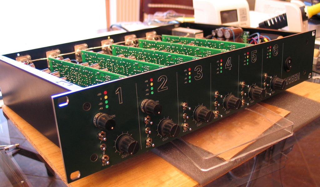
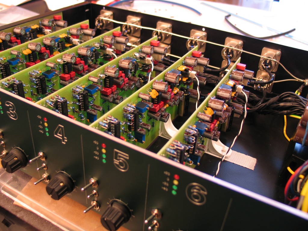
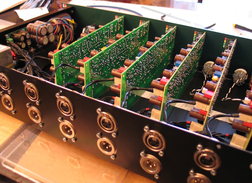
Here are few pics:


If someone wants to hear it, I can post samples of the beast...
Cheers!
Younes
Just a little word to say a big thanks to Peter for sharing this great project.
I did it few month ago and I must say that it has becomed one of my favourite pre!
Here are few pics:
If someone wants to hear it, I can post samples of the beast...
Cheers!
Younes
peterc
Well-known member
do you think I need to replace the lm317 that got so hot?
I dint think so, it would have gone into thermal shutdown, so if it is working, should be good.
Yoons
Nice build!
Phrazemaster
Well-known member
Actually I took a closer look at the 317 and the bottom half had melted inwards...Yet it was still working!
I replaced it anyway, and some of my voltages are slightly lower overall, but still getting 48.5v on the phantom rail.
I'm excited because although this is just the PSU, IT WORKS!!! This is my first project like this, so I'm jazzed!!!
Thanks Peter!
Yoon, I must echo Peter's sentiment: ROCK SOLID!! What an inspiration!!
KasperNyhus
Well-known member
Hi Peter!
I would also like to know if you have got more boards?
Planning to build an 8 ch unit...
Kasper
I would also like to know if you have got more boards?
Planning to build an 8 ch unit...
Kasper
Phrazemaster
Well-known member
Wow, you 8channel folks are brave! Just be sure your psu can handle all of it.
Similar threads
- Replies
- 1
- Views
- 378
- Replies
- 57
- Views
- 5K


![Electronics Soldering Iron Kit, [Upgraded] Soldering Iron 110V 90W LCD Digital Portable Soldering Kit 180-480℃(356-896℉), Welding Tool with ON/OFF Switch, Auto-sleep, Thermostatic Design](https://m.media-amazon.com/images/I/41gRDnlyfJS._SL500_.jpg)


