Altec 438C repair help needed

GroupDIY Audio Forum

Help Support GroupDIY Audio Forum:

This site may earn a commission from merchant affiliate links, including eBay, Amazon, and others.

dustbro

Well-known member
Joined
Feb 1, 2006
Messages
665
Location
New York - USA
Here's my story... and I'm sticking to it.  ;D
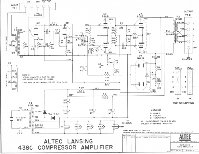
I have an Altec 438C that was in wonderful working condition. My only complaint was that it didnt have any output control, so I decided to add a T-pad attenuator on the output. I realized after the modification that I didnt wire the t-pad correctly so it wasnt working as expected. I was in a hurry to use it in a session, so I removed the attenuator and took it into the studio. Everything worked great for about 30 mintues.... then the unit started to make everthing sizzle (sonically). Then I noticed that the GR meter was just sitting at -5dB instead of 0. The meter does move when the input exceeds the threshold, but always rests at -5dB.
Voltages are a little lower than whats on the schematic, but well within the 20% limit. I swapped all of the tubes with no cure.
Pulling V3 (6CG7) makes the meter rest back at 0.
Could my botched output mod have messed up my comp, or is it just a coincidence?

altec438c.png
 
This comp is driving me nuts. Everything seems to be as it should, except all of the voltages are low. At the point where C12 and R20 meet, I'm getting 180V instead of 255. Is it possible that the rectifier is not working as it should? Or does this diode just stop working when its broken?
 
just answered my own question. I replaced the original bridge with a pair of 1n4007 and got the same low voltage. I noticed that as it powered up, the intersection of c12 and r20 started at 255 and then made a decline to 180V. pulling V3 brings the voltage at back to whats listed on the schematic.  ???
 
dustbro said:
This comp is driving me nuts. Everything seems to be as it should, except all of the voltages are low. At the point where C12 and R20 meet, I'm getting 180V instead of 255. Is it possible that the rectifier is not working as it should? Or does this diode just stop working when its broken?
Fault would not seem to be (directly) related.

The only regulation in this circuit is natural voltage drops due to current. If you measure other points along the chain you'll also be able to work out the current consumption of each branch compared to the values on your schematic (V drop across each resistor = IR). That might give you a clue if anything is drawing too much / too little current compared to the schematic.

A diode rectifier would normally fail for 100%. Could be that one half of the half wave is not delivering. You can always remove the diodes and test them in isolation to see if one has failed. Standard component test. A transformer would also normally fail 100% but you could check that the windings are still reading the same impedance (without any power connected of course). HT capacitor could have gone leaky (ohmic). I probably shouldn't have to write this but I'm going to anyway: Be careful when testing the HT circuit, because even with no power applied the capacitors may still be holding a (potentially lethal) charge.
 
dustbro said:
just answered my own question. I replaced the original bridge with a pair of 1n4007 and got the same low voltage. I noticed that as it powered up, the intersection of c12 and r20 started at 255 and then made a decline to 180V. pulling V3 brings the voltage at back to whats listed on the schematic.   ???
Well that would point to a problem with self biassing and drawing too much current. Check the cathode to grid voltage of both halves of V3. Loose connection around R13 or R11/R12 would be a suspect. Grid should be at ±0V of each half, held there by the 1M resistors R11 and R12. A cathode voltage of ±2.3V with 145V on the plate (from the schematic) should give a bias current of around 10mA.

Oh and check the continuity of the primary winding of your output transformer and the plate voltage of both halves too. If only one half of the 6cg7 is getting plate voltage that'd screw up the biasing too (as the common cathode voltage is due to the sum of the currents through the two halves of the tube).

You might want to break the feedback loop at C8 into the side chain until you get the signal amp stable to ease debugging.
 
Thanks for the advice and safety warning! I'm definitely the kind of guy who starts poking around HV without thinking first...
So I started poking around and found that the point where R16 and R6 go to ground was broken, so I repaired that and it seemed to fix an issues I had with my noisy input pot  ;D
How does one check the "cathode to grid" voltage?
With referece to ground, I have the following voltages on V3
1 - 108v
2 - 0v
3 - 2.2v
6 -108
7 - 0v
8 - 2.2v
with my multimeter leads between pins 2 and 3 I get 2V and with my leads between pins 7 and 8 I get -2V.

thanks again for the help! I need it

 
I'd actually try a few different tubes in V3 position first. I've known these machines to be quite demanding of tubes in that position.

If you can measure the plate current safely on each half of V3 it might tell you something.

 
Ok. I'll try another tube to see what happens. I was just going thru the unit to make sure that all of the points that are supposed to be grounded actually are... is it normal for the tube heaters to have continuity with ground? My multimeter is beeping on the heater pins.
 
MagnetoSound said:
I'd actually try a few different tubes in V3 position first.

I tried 3 tubes. All with the same results.


MagnetoSound said:
If you can measure the plate current safely on each half of V3 it might tell you something.

Any recomendations on how? I'm reading online that it involves a 1ohm resistor?
 
dustbro said:
Thanks for the advice and safety warning! I'm definitely the kind of guy who starts poking around HV without thinking first...
So I started poking around and found that the point where R16 and R6 go to ground was broken, so I repaired that and it seemed to fix an issues I had with my noisy input pot  ;D
How does one check the "cathode to grid" voltage?
With referece to ground, I have the following voltages on V3
1 - 108v
2 - 0v
3 - 2.2v
6 -108
7 - 0v
8 - 2.2v
with my multimeter leads between pins 2 and 3 I get 2V and with my leads between pins 7 and 8 I get -2V.

Well you either measure it directly with a multimeter, or you measure all pins to ground and do a subtraction. You've done both which is fine.
Just check once again the sign of the measurements you quoted for the direct measurement of pins 2-3. Pin 2 should be more negative than pin 3. Pin 7 should be more negative than pin 8. I think it's OK based on the other measurements, but you said you got +2V between 2 and 3 and not -2V.

Hmmm.

For the two halves of V3 6cg7 you have:

anode/plate 1 - 108v
grid 2 - 0v
cathode 3 - 2.2v

anode/plate 6 -108
grid 7 - 0v
cathode 8 - 2.2v

anode voltage definitely looks too low compared to the schematic.
Cathode voltage looks good (relative to the low anode voltage).
Grid looks good (0v)

So you have 2.2V/220R = 10mA of total bias current, which is spot on.

The overall anode current can also be measured as 180 (V@R21) - 108 (V other side R21) /7K = 72/7K =10mA
Glad to see it matches the cathode current = no shorts or leaks to anywhere else.

But an additional 10mA through V3 should not cause such a huge drop from 255V (load excluding V3) to 180V (load including V3) out of your power supply at the junction of R12 C20 IMHO. That's 75V drop for 10mA load, or a power supply with an internal resistance of 7K5 which is way too odd.

Another easy test to confirm or exclude this suspicion raised by your previous comments about this voltage drop when v3 is inserted or not:

Can you turn the compressor on with V1 and V2 inserted but not V3 inserted and measure the voltage at the junction of R20 and C12 relative to the chassis?

Tip: suggest connecting up your multimeter before turning on the power so you don't have to move anything inside the box whilst the power is on.

The initial peak no load voltage could be as high as (117 * 2 * 1.414) = ~ 330V. Once things settle down it will be lower than this.

Remember that no significant current will flow until the tubes/valves heat up, so you're probably gonna have to wait 30 seconds or more before you measure stable voltages.

Check if the voltage at the junction of R20 and C12 stabilizes at 255V with V1 & V2 inserted but not V3 (as you previously wrote)

Turn off. Be patient and don't burn your fingers on hot tubes. Go and have a cup of tea in the meantime :)

Then repeat with V1 V2 V3 inserted and see if it really does reduce to 180V (again as you previously wrote)

If so that would really turn the spotlight on the voltage doubler and PSU.

Based on that I would suspect the voltage doubler then (the 2 diodes and the 2 capacitors in the Delon circuit C12 C13 http://en.wikipedia.org/wiki/Voltage_doubler) as well as C110. You say you've replaced the diodes, so I'd look at the two power caps (safely discharge them first via say a 22K resistor across the terminals without touching any terminal with your hand) You could also check that when powered up that the voltage at the junction of C12/C13 is (almost) exactly half the voltage at the junction of C12/R20. If it isn't, then the cap with the significantly lower voltage drop may have gone leaky. A 100uF 400V power cap is only going to cost less than $10 to replace if that's the issue and you don't mind using a non-vintage replacement.

Now if you need to measure the balancing: There's no real way to do this easily on this compressor. You can either place your multimeter in series with one winding of the output transformer and the anode in current measurement mode in turn to measure the current directly. Or you can insert 100 ohm resistors in series between the anode of each half of the valve and the corresponding tap of output transformer (pin 1 to red & pin 6 to red/white) and measure the voltage on either side of these resistors to ground. With 10mA of total current you'll only drop maximum one volt across this resistor even if it is 100% unbalanced.... Current in each leg = (V anode - V output transformer)/100). They should match for proper operation. Normally this occurs pretty naturally due to the natural negative feedback within the valves themselves, but it could still be faulty/ non matched valves.

So I'd concentrate on the power supply side first as it's an easier test, and you've already tried 3 different valves.
 

Latest posts

Back
Top