Another Amek Tac Scorpion overhaul!

GroupDIY Audio Forum

Help Support GroupDIY Audio Forum:

This site may earn a commission from merchant affiliate links, including eBay, Amazon, and others.
mitsos said:
I'm sure Colin stocks decent caps, but, personally, I would not buy hundreds of caps unless I had already tried them them in a couple of channels.  There are audible differences between different caps, some more obvious than others.  I only mention this because it seems like you plan on using this mixer in the future, and you could be doing yourself a disservice by not auditioning a few different types.

I hear you! I'll test 4 channels which I'll do up like Graham intended, together with his upgraded mic input amp, I'll do a couple with his lin-amp input too. and the rest I'm going to experiment with! I'll try those Silmics for sure!!
 
mitsos said:
But, yes, stop everything for now and do the PSU first.

Just ordered all part for PSU from Colin!!
The master scection capacitors and 4 preamp-kits should arrive today.
 
Somehow I'm always surprised that it takes two mailmen to deliver my mail, the first guy bring everything he thought he had to deliver, and a second one brings everything he forgot! So it was the second guy who delivered AML's box of caps this morning!
Alas, I only did order the master sections caps and 4 mic preamps from Colin, but as we speak the caps for the power supply are being shipped here as well!

I was happy to have bought my de-soldering station last time I did a job this big, and again it saved me a lot of time, hassle and headaches to get the caps of without breaking traces or pads! This i something, and I don't mean to bring this guy back up, but he managed to break quite few around the mix-bus and fader-booster section. But no harm done, once the master section was uncapped and all those shiny red caps were mounted I managed to sneak in a single s1000 channel too this afternoon. You should know that I'm currently living with my wife, a 19 month old and 1 week old daughter, so there's little time left for daddy to do what he wants to do.

11134045_649977775134059_4253463998507910294_n.jpg


11129633_649979598467210_1770279048712154536_n.jpg
 
I don't seem to get the audio from the channelstrips to the master section? It does through monitoring/PFL and through the insert return there's audio to the fader, but in between it goes nowhere.

In the schematics I see that the mix bus get audio from the virtual earth input, but that's new to me...
only master section and two channels in the frame... I don't get it

EDIT:

and then it became even stranger.
when putting a channel into group 7-8 it goes through 8 to the mix bus.
 
Is the stereo send button pressed on the channel?  (right above the pan knob)  If you get signal in the groups and from there to master, the channel is working and so is the master.  If the switch does nothing, either bad switch, bad resistor network (doubtful) or bad solder joint in that area.  IIRC the stereo bus is on pins 31 and 32 of the connector, double check on the S4000 schem.
 
mitsos said:
Is the stereo send button pressed on the channel?  (right above the pan knob)  If you get signal in the groups and from there to master, the channel is working and so is the master.  If the switch does nothing, either bad switch, bad resistor network (doubtful) or bad solder joint in that area.  IIRC the stereo bus is on pins 31 and 32 of the connector, double check on the S4000 schem.

No totally different, and stupid, but I thought it wouldn't matter! Because I didn't have the face plate on the master section I stuck it in a slot to the left instead of its own... figured it out when I thought it trough. Should have done that before I stuck it in there!!
So it's working now!
 
I managed to recap two more channels yesterday! And what should have been done before all else, but now is just as good a time as any, would be a PSU rebuild. Every topic I have read about a TAC scorpion mod started with "Do the power supply unit first". So here goes!!

Stuff to do:
  * Cleaning, because it looks as if a rat died in here!
  * Uncap all electrolytic capacitors
  * Remove the TO-3 sockets for the LM388K, LM317HVK and MJ2955.
  * Fit insulating layer between the heatsink and the PCB.
  * New cooling past and TO-3 insulators
  * Recap all electrolytic capacitors
  * Break something
  * Trial and error
  * Replace burned resistor which I didn't spot because it was hidden!

So we needed to get the PCB out of it's enclosure, and not thinking clear I removed the fuse holders as they prevented me from lifting the board out of the box. Ok, I could have unscrewed the front plate, I didn't think of that! Anyway, that front plate will need replacement someday because the previous owner moved the power connectors to the front for easy access, I would like them in the back, where they belong.

20879_651380094993827_5938113066615285118_n.jpg


Next we de-soldered all the electrolytic caps, removed the heatsinks and cleaned the PCB to get a fresh start for this puppy! As it turned out two of four TO-3 sockets were broken so it's a good thing I got pushed to remove them! You need to unscrew the TO-3 sockets, de-solder the two pins on the bottom of the PCB, and 1 pin on top. This last one is the actual metal housing, and the output of the amplifier/transistor. You need to remove that pin because the heatsink will otherwise bump into it when you try to put it down on the PCB.

I didn't have the TO-3 insulators yet, nor the cooling paste or any means of insulating the heatsinks from the PCB, although I don't see why you just couldn't fit them to the pcb, as it's a single layer circuit board. So I recapped the PSU-board.

10929974_651380131660490_2338911859480169802_n.jpg

(edit: nobody saw me messing up the polarity on that big axial cap!!)

It turned out that my local electronics shop does not have insulating slabs in stock, that happens to me all the time, and that's the main reason I order everything online, because that local shop is a waist of my time, cause it usualy takes half an hour for them to get back to you and say they don't have it! So we had to improvise.

I happen to be kind of a greasemonkey too and I remembered I had some G3900 gasket board laying around in my workshop. I used the gasket board as an insulating layer between the PCB and the heatsinks, and pretty sure there will be no leaking either!

11114266_651380181660485_2846057646845276139_n.jpg


I managed to get everything lined out, and bent some thick component lead leftover to use as a connector between the TO-3 shields and their output traces. You can then solder the other pins to the board. No more Sockets no chance of these to come loose!

10308559_651380188327151_1889970637051233663_n.jpg


Before soldering I cleaned the heatsinks and the TO-3 packages. I applied new cooling past and fitted new bolts to put everything pack into position.

11162203_651380234993813_5918469503000888760_n.jpg


After breaking two of the fuse holders when refitting them and replacing a bad resistor I did not spot before I was ready to refit the board. Only thing left was to hook everything back up and measure the voltages. After that I plugged in the scorpion and everything worked as it should!

11150860_651380238327146_8073281925605630896_n.jpg


All information regarding a PSU rebuild I found:
  * Schematics *note, C2 is the big 10,000uF cap next to C1! Wrong marking on the silkscreen. This is the schematics for a 750 PSU, in my original manual there's only a 350 schematics?!
  * Colin's TO-3 socket fix.
 
Don´t forget to check the rectifier. I once had a PSU on my bench with totally overheated rectifiers. The epoxy was falling apart when touching the wires/contacts. Fit some new thermal grease underneath it.
If you think about opamp upgrades then your PSU will see more current load. This will heat it up more than with the desk in original state. Think about adding a fan inside. The PSU case is prepared for that, that´s the cool part about it. There are some very low noise, slow running fans available. Run the fan from mains, not from the audio rails!
 
Cool project!

I recapped my Scorpion II with Elna Silmic IIs and it is sounding better. I've been stuck working 80+ hours a week for the past 8 months, so the rest of the project has been put on hold. I have a switching PSU that came with the console. So the first step is to finish building a better linear PSU with more amps so I won't have to worry about swapping out ICs in every channel.

I really wish Audio Maintenance would sell individual pcbs instead of kits. I'd love to upgrade the preamps with his, but it's not worth it to me to spend that much buying the kits. I'd rather buy all the pcbs and order parts from Mouser whenever I have the money.

After the PSU, I'm upgrading the summing to the ACA-BO like Mitsos suggested. I'm pretty excited to hear the difference that makes.

If you could, try to post some before and after running through the new line or mic preamps compared to stock. I'd love to hear it.
 
jensenmann said:
Don´t forget to check the rectifier.

Good point!! I noticed there is one that's not screwed tight, and when I turned it around I thought I saw some thermal grease! I'm cleaning that up as we speak! good thing I bought enough cooling past to last me a few years!!

jensenmann said:
If you think about opamp upgrades then your PSU will see more current load. This will heat it up more than with the desk in original state. Think about adding a fan inside. The PSU case is prepared for that, that´s the cool part about it. There are some very low noise, slow running fans available. Run the fan from mains, not from the audio rails!

There is a fan inside, but I think it's dead, as it's not running when I power on the PSU  :eek:
I'll have to source a new one!

critterkllr said:
I really wish Audio Maintenance would sell individual pcbs instead of kits. I'd love to upgrade the preamps with his, but it's not worth it to me to spend that much buying the kits. I'd rather buy all the pcbs and order parts from Mouser whenever I have the money.

Colin is not selling the preamps as a kit, they have been put together! That's why they are a bit more expensive then the PCB + parts. You only need to remove some components from your Channelstrip, plug in the new preamp and solder it! done.

critterkllr said:
After the PSU, I'm upgrading the summing to the ACA-BO like Mitsos suggested. I'm pretty excited to hear the difference that makes.

Yeah, I hate mitsos for putting that idea in my head too!  ;D
But I'm not convinced yet, I need to figure out how to implement it the right way! The way I see it, the first stage of the ACA-BO replaces the Mix-Bus circuit, that's easy, the second part would be replacing the original fader booster circuit and balancing the outputs to my recorder/DAW for tracking the end result. But I would not be listening to the same sound unless I feed my monitoring with the same signal.
The original circuit takes the mix-bus signal to the monitoring before the fader booster, or am I looking at this the wrong way?

11113901_651748474956989_190064392661317847_n.jpg
 
critterkllr, I wondered if you scrapped the idea.. I'm hoping to get moving on mine towards the end of June or so.  Too much other stuff to do til then. 

Eliani said:
jensenmann said:
Don´t forget to check the rectifier.

Good point!! I noticed there is one that's not screwed tight, and when I turned it around I thought I saw some thermal grease! I'm cleaning that up as we speak! good thing I bought enough cooling past to last me a few years!!

Does anyone know of Fast or soft-recovery rectifiers in a simialr package (at least similar faston type lugs?  I ask because I saw that company GRS that rebuilds TAC psu's claims to swap them, but I can't find anything at the normal distributors.

jensenmann said:
If you think about opamp upgrades then your PSU will see more current load. This will heat it up more than with the desk in original state. Think about adding a fan inside. The PSU case is prepared for that, that´s the cool part about it. There are some very low noise, slow running fans available. Run the fan from mains, not from the audio rails!

There is a fan inside, but I think it's dead, as it's not running when I power on the PSU  :eek:
I'll have to source a new one!

FWIW, there is a thread at GS about swapping opamps, somewhere in the middle is an estimate that the increased current consumption is about 0.25A when swapping U5 and I believe U1 in the inputs, plus relevant ICs in groups, aux and master modules, in a 32 channel board.  My PSU has a fan running off AC, and it's noisy.. With the socket removal mod I hope to be OK installing a low noise DC fan meant for PC cases and see what happens.  Besides, my board is 24/16/2 and I have the large scorp PSU, plus  I'm going to remove a bunch of the groups, so much less current consumption.  I'd rather abuse the PSU a bit and save my sanity.

critterkllr said:
I really wish Audio Maintenance would sell individual pcbs instead of kits. I'd love to upgrade the preamps with his, but it's not worth it to me to spend that much buying the kits. I'd rather buy all the pcbs and order parts from Mouser whenever I have the money.

Colin is not selling the preamps as a kit, they have been put together! That's why they are a bit more expensive then the PCB + parts. You only need to remove some components from your Channelstrip, plug in the new preamp and solder it! done.

If someone can help me finish my input PCB, I'd be willing to do a group buy on the PCBs. IIRC, I got hung up on how to switch from mic to line, but the idea is a trafo-in discrete opamp  (or IC opamp) preamp, with differencial line receiver input. 

From the aprts used, the AML kit looks similar to the Amek 2500 input, you can always try to design a PCB for your own use of that, or another favorite circuit.

critterkllr said:
After the PSU, I'm upgrading the summing to the ACA-BO like Mitsos suggested. I'm pretty excited to hear the difference that makes.

Yeah, I hate mitsos for putting that idea in my head too!  ;D
But I'm not convinced yet, I need to figure out how to implement it the right way! The way I see it, the first stage of the ACA-BO replaces the Mix-Bus circuit, that's easy, the second part would be replacing the original fader booster circuit and balancing the outputs to my recorder/DAW for tracking the end result. But I would not be listening to the same sound unless I feed my monitoring with the same signal.
The original circuit takes the mix-bus signal to the monitoring before the fader booster, or am I looking at this the wrong way?
[/quote]
IIRC this is how it's done.  Won't be able to test again for a couple of months, though.
Remove C4, C28, R55, and C34  (NOTE: R55 is probably supposed to be R54, this is what I meant that the schemo has errors, all right channel components should be even numbered, IIRC).
Then, using shielded cable with shield tied to ground on one side:
Circle 1 is where you take the signal to the ACA, Circle 2 is where it comes back to the master module so it can go to the insert and fader.  Circle 3 is where it goes to the booster and Circle 4 is where it comes back again. 

The signal goes to the TAC's monitor outs after the 47R output resistor, whether or not you use the ACA-Bo, so you'll have one more IC in your monitor path with the stock version.  If you want to monitor directly (you'll lose separate level control, but some people use external CRM systems, if so, then I think it's better to skip the ICs), you can mult the ACA-bo output direct to the monitor outs, (the ACA-Bo has two connectors per output), or use the other trafo isolated output, but your monitor would be at -6dB with respect to the main out).
 

Attachments

  • TAC_ACA_mods.png
    TAC_ACA_mods.png
    243.4 KB
Mitsos,

Looks right to me, I'll have a closer look tomorrow!

Concerning the input pcb I prefer DOA's like 990 or 2520, I'm thinking Lundal LL1528, and we'll get on a board, like 8 channels or so per PCB. You can bolt it to the bottom of the frame in the back, use the ribbons to hook it to the patch and wire it to the channel with a sub-pcb of some sorts!
 
So together with the sonic improvements I feel the scorpion could do with some aesthetic upgrades., and an easy thing to do is to replace the 4mm pot knobs! or so you would think. I've got some API knobs laying around but they did not fit, I guess they are 1/8th of an inch. Even if they did fit, I wouldn't feel right having them on a true Langley channel strip! So I bought some cheap Davies knobs online, I'll surprise you with which ones when they arrive. These knobs are for 6mm pot meters so I needed some kind of flange to go from 4mm to 6mm and found something at Mentor! (KR 4-6M)

11169935_652206721577831_8104910348002535598_n.jpg
 
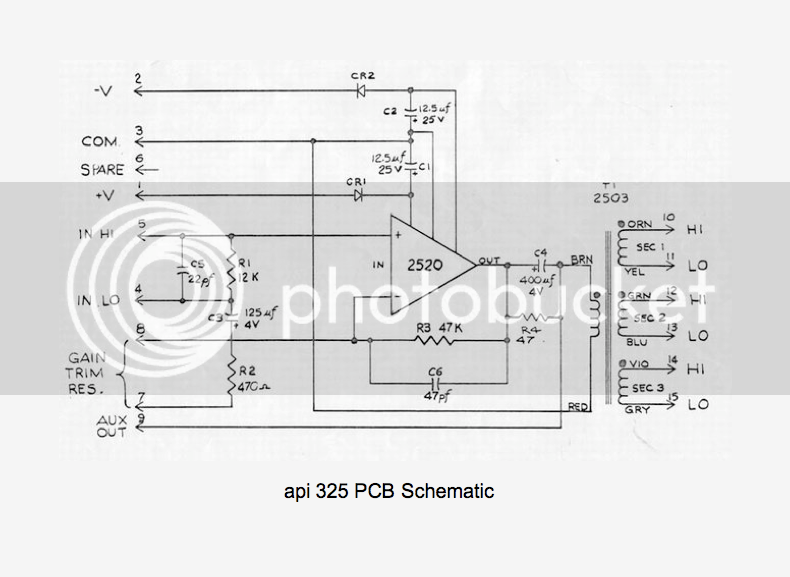
If I were to install an 2-ACA-BO summing/booster upgrade, I would like some API style line inputs too! So I'm looking at the 325 line/booster/combining amp card. As they are hard to get, even without DOA's I would like to make some PCB's containing up to 4 Line-in circuits. I can see a hand-full of schematics, including the original, the proposed schematics for line-amplifiers in the 2520 brochure, and Jeff's booster circuit. I'm trying to poor them together to build an economical, but true to the original solution. I can see why 47uF instead of 12,5uF would do a better job on decoupling the power rails, and Jeff looses the CR1 and CR2 rectifiers for 100R resistors (This I don't get, but then I'm not very good at this!)

The biggest problem I face is to find an economical substitute for that 125uF cap towards the gain trim,  or is this an important  value and I should just keep it? Or should I use the 312 style input? Or should I just quit this whole project, or buy 2-stage line amps from Jeff?

If I think about it there are few facts I should keep in mind before spending to much money on this!
  * I should not stuff this little console with fancy preamps, but build API 500 pre's instead!
  Why? They keep their value and nobody is going to pay for stuff hiding in an old recording console if I decide to sell it some day!
  * Keep building from the finish line to the start, PSU/Master section/Summing/Groups/Channels.
  Why? There's no point in running 32 boutique channels through a pigsty of a summing mixer!
  * I would like to buy an API console, but I never will!
  Why? Because I keep spending my money on this stuff!
  Do I care? No, because I just love audio electronics, even if half the time I have no clue what I'm doing, I should have picked electronics in school instead of metal fabrication, because I still suck at the last one, and enjoy this a lot more!

Anyway, I'm committed to this so Jeff you might get an order in soon.

325drawing.png
 
So we change a few bits around and came up with this.

11160660_652884224843414_2259482589016728787_n.jpg


I'm sure this is right for now, it's almost a true copy of that 325 card, just changed a few values and left out the balancing transformer. Just don't know what to do with that hard to get 125uF, I guess I'll just make it 220uF and test it! I would love to get this to stick to an eight channel PCB, but it would be hard to get it to the channelstrip board. I guess I could make a sub-pcb like AML's micrpe upgrade.
 
If you want a true line input you should either use a 312 type PCB but with a 10K:10K input transformer or step-down, maybe 10K:600 or so.  Or, wire the 2520 as a differential amp, like number four in the attached file, but lower the Rf and the shunt R to 10K for unity gain.
 

Attachments

  • api2520_02.jpg
    api2520_02.jpg
    164.3 KB
gar381 said:
Eliani..  Use a 220uf/16v or even LARGER uf.  BC/ Vishay axial cap ( the Blue ones).

It will work fine!! :) :)

GARY

Thank you Gary! I'm going to use your gar2520 and gar1731 opamps for this mod. It would just be nice to have a european supplier for them, unless there is and I look like a fool!
 
Just ordered the 2-ACA-BO PCB, 4 gar2520 kits and two 2623-4 transformers and an additional 6 gar2520 kits for the 325 line-amps from Jeff!
 

Latest posts

Back
Top