API 312 Thread!

GroupDIY Audio Forum

Help Support GroupDIY Audio Forum:

This site may earn a commission from merchant affiliate links, including eBay, Amazon, and others.
There is a lot of good info on Fabio's site. But, the 2520BC is probably wrong as many people have had oscillation issues with it.  There is another recent thread about this opamp.  People that seem to have worked it out are Scott Liebers (SMD version) and Peter Purpose (through-hole). I believe Fabio may have a new version which is being offered soon in the Black Market and should be different than the 2520BC on his site.
Didn't know Fabio had an original style 312 board there... handcrafted tone also has one. Maybe compare the two, if they are the same, they are probably correct.  But you can find a much less complicated PSU than Fabios. The SSL9K psu board for example, or PeterC's.

As far as trafos, jsteiger has a site offering API remakes designed by Ed Anderson (who really knows transformers). That may be your best bet, and then there is Cinemag, although I would disagree with Bob's recommendations above. About the 75101, it will work, but is not the original ratio.  The CMMI-8 is the one you want if that's your thing.  You can also save a few $$ and get an Altran 3402-2.  I have used them and they are very nice.
Outputs: Cinemag CMOQ-2S (Bob recommended the CMOQ-2L, which may be nice and will def work, but it is high nickel, not what API used in the past.)  The Altran version is C-3865.

You can order any of these trafos direct.
 
Jensen also has the JT115K (I think that's the correct model number). Expensive, but is an actual part number shipped with API units in the past AFAIK.
 
bobschwenkler said:
Jensen also has the JT115K (I think that's the correct model number). Expensive, but is an actual part number shipped with API units in the past AFAIK.
I believe you are correct on that. They have also used JE 110K, 6110k-a and the 75101 in the past, all since the AP2622. I wonder why they've made so many changes over the years? I suppose all the new ownerships and what not may have something to do with it.
 
mitsos said:
There is a lot of good info on Fabio's site. But, the 2520BC is probably wrong as many people have had oscillation issues with it.  There is another recent thread about this opamp.  People that seem to have worked it out are Scott Liebers (SMD version) and Peter Purpose (through-hole).

I have the 2520 r1 boards. This may explain why I was sent these instead of the BC boards although I purchased the (BC550/560)parts. So I am wondering are the boards the same accept for the componant types as I have put in the BC parts. They seem to follow the same schematic.

Could the oscillation have something to do with the boards themself.
 
hey guys, sorry if i missed info on this somewhere.

just got 2 channels of fabios v3 finished/racked. everything is gravy, EXCEPT....

when i turn phantom power on, i start getting intermittent static/popping noise. any ideas?

also, a couple other questions....i am using JH990Cs for the opamps. it works, but i just want to make sure i dont need to make any changes in the circuit for any reason. i have them running +/-18V.

also, i am using 24V relays. i have the JLM 5 rail powerstation. for the relay, i just change the rail to +24V correct?
thanks,and sorry again if this has been covered.
 
Hello everyone ,

I ve done 6 api 312 from Fabio board,
2 with Cinemag 75101APC input and cinemag CMOQ-2S output transformers with DAO from Fabio
2 with Cinemag 75101A input  cinemag CMOQ-2S output transformers with DAO from Fabio
2 with cinemag 75101APC input and Fabio output transformers with DAO from Fabio

Sounds great but i was a little surprised to see that i was unable on protools Tdm to clip 0 DB FullScale !!! 
It seems than the preampl clip themself before , Typically on a snare i can see it clearly ...

What's wrong with them ???  any idea of what i should look for ??

Thanks
 
Flight, I would look at the gain switch setup.  I have to pad the hell out of my API's to tame the input of PT.
Maybe a transformer is backwards?

Maybe you have to insert a PAD so the preamps don't clip.
 
How are the transformers wired? Especially if the input is at 1:10 and the output is at 1:2 you should have more than enough available gain from the amps to run out of converter headroom.

Whatever it is, it's almost certainly an issue with the amp stage. What voltage are you feeding it and what amps are you using?
 
hey guys,

so, both my channels are working great. however when i turn on phantom, about a second later, i get (now) constant noise. like a mix between crackling and white noise. the other channel stays quiet (unless i turn its phantom on as well).

the voltage across pins 1 and 2 stays a solid 48.4 volts. i turn phantom back off, and the noise stays until the voltage across pins 1 and 2 falls to around 10V. then its all good again.

i measured the ripple with a DMM set for AC, i get .007 volts. it stays constant once i turn phantom back on.

the only thing i can think of (in my little to no experience) is maybe CPP1 (im using fabio's boards) is bad (although, it behaves identically on both channels)

any ideas on the problem? im not expecting anyone to solve it for me, im just looking for a way to pinpoint my searching.

thanks.

 
Hard to say... I had problems with phantom before that turned out to be a faulty ground scheme. how's your grounding?  Put together a star-ground scheme if you don't have one already. It may not solve this, but it can't hurt.

Good luck.
 
bobschwenkler said:
How are the transformers wired? Especially if the input is at 1:10 and the output is at 1:2 you should have more than enough available gain from the amps to run out of converter headroom.

Whatever it is, it's almost certainly an issue with the amp stage. What voltage are you feeding it and what amps are you using?

Transformers wired correctly i suppose , the same color than on the Fabio Pcb ...corresponding to Cinemag transformers output

Im feeding +-18V To the Amp Stage using 2520 From Fabio ( What other DAO could i Try to see if problem came from 2520 Fabio )
and i Use a 1 Pole 12 Position for Gain ( Using resistances )
 
bobschwenkler said:
Do you have pin 1 chassis grounded and your chassis grounded to ground?

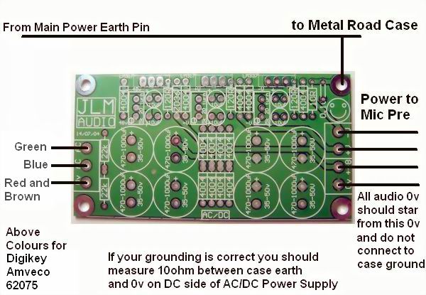
i have the grounding like this photo. all pin 1 of input/output xlrs, as well as the 48v ground on the board go to the common 0v (where it says put all audio grounds). i hope this is correct, i do measure 10ohms between common ground and case ground.

JLMACDCwiringDigikey.jpg


ive been changing the ground scheme around trying to get this to stop, no success.

i HAVE found, however, that with a condenser plugged in and phantom turned on, it works perfectly...dead silent. it is only with a dynamic mic plugged in, and phantom turned on that i get the noise. obviously, it is useable since i dont need phantom for dynamics, but none of my other pres do this. 

any help appreciated, back to testing i go.
 
I had a nice reply writted out and when I went to post it, it gave me an error. So here we go again from memory... Ryan, grounding is tricky. What might work in some situations may not work in others. Unless you adhere to a strict star ground scheme, which I think you are not, by the fact that you mention you have run the 48V ground to the PSU pcb. If you have more than one ground wire going from a board to the star ground, you have a loop and potential cause of problems.  There should be one and only one ground wire from each and every thing (Except output XLRs, those should be left unconnected, otherwise you could cause a ground loop with the next piece of equipment in your rack).

1st, your case must be connected to earth (third pin of the power cable MUST be securely connected to case by a short fat wire at all times!) This is a non-removable, non-liftable ground connection.

Next, run a short wire from each input XLR pin 1 to the case (you could also run it to the star ground, but the shields are part of the case, so best to keep them there, I think). Both ways could work depending on the situation, but the first one is more sure to work.  If you use shielded cables inside your case, connect them to the pin 1 but not to the board.

Then, take ONE wire from each preamp board to the 0V of the PSU (pick which one, it doesn't matter since it is the same ground plane under there). The JLM PSU gives you a convenient spot for an audio ground lift if you replace the 10R resistor in the upper left of the board with an SPST switch. But you want to make sure that the bolt going through that corner of the PSU PCB has a solid connection to the board and case. Scrape off case paint, clean the metal, do whatever you have to do to get a good connection.

Once you have your audio grounds connected together (at the 0V in this case) and and you want to do the ground lift thing, just stick the switch in place of the resistor. . I'm sure Joe has a good reason for putting that 10R there, but it's not common practice so, personally, I'd remove it.

So now you have your audio ground and your case ground done properly but separated. If you want to do the switch thing, just put it in place of the resistor and run it to the back of the case so you can lift the audio ground (but never the electrical ground) as you need.

Hope that helps. If in doubt post some pictures of your wiring. I may have gotten this all assbackwards but you'll get it right in the end.  Try to search for ground problems here or visit this site for some links:
http://pin1problem.com/
 
OK, so I designed a 312 board (seems like the thing to do these days....) and am having a serious problem. I got one board "milled" and it sorta worked except the guy used a crappy drill bit and ate some of the thinner traces. No biggie just meant no polarity and phantom was messed up too. So I went back to etching, got a decent etch, drilled, stuffed, tested my DC with a known good supply, +-18V and phantom ok. Turned it off, drained the caps, and plugged in an opamp (tried a melcor and a JH990).

My schemo is a bit different, has a 47R series resistor on the output, in parallel with 2 caps. Saw it on a 212 pre and the eisen audio pre. Anyway, the first time I turned it on, the R12, the 47R started to smoke immediately. Turned it off, and thought I smoked the hardy 990. Haven~t had the courage to try it in a working board to make sure. I reconnected everything and tried again, this time the 7818 regulator smoked and died. Cracked the casing and everything.  So I swapped both the regulator and 47R, tried again with the melcor and the 47R started to smoke so I immediately turned it off. I am curioous to see what kind of voltage is coming out of the opamp, but I'm on my last regulator so I don't want to blow it up by leaving the power on too long (to test voltage). 

I am thinking there is a short to ground on the positive rail but I can't find it. All the components were removed from the first (milled) board and installed here, so I think they are ok. But I am at a loss as to what would cause R12 to smoke like that. Any help much appreciated.
 

Attachments

  • schemo.png
    schemo.png
    22.2 KB · Views: 196
Mitsos.  If you are using a transformer you don't need all that junk on the opamp's output.  Plus the resistor and caps are making a boost of all frequencies above 15HZ (oUCh!!).

Look for Bo's schem and JLM's Baby animal.  just a cap on the output is OK but not necessary.  Eisen's describes the 47R you have as being a simple jumper.
 
I don't follow the boost in everything above 15Hz..?  If anything I would think it would cut frequencies, but you'd need to have one in series and one in parallel, no?  I thought the caps are just coupling, to eliminate DC if it's there, etc. I know some people run these with no output caps, but I've tried both and this way sounded best to me. Granted the Eisen is a bit different, but the 212 schemo is exactly like this. Eisen actually has a spot for the 47R, and after that has the parallel caps. I figured the way it is in the API 212 was better for me since Jens builds his stuff to become 312, 512, or M1s, or whatever else, so he includes choices.  The parallel resistor is indeed a jumper on his board but only when you don't use a cap.. hmm. OK, funny thing is that it worked on a modified handcraftedtone board and on the milled version of my board, but not on the etched board. The only differences between the two boards is phantom/polarity should work (with no power I got continuity in the right traces while playing with the switches, and I flipped tw resistors horizontally so that I could get the traces between them more easily. Other than that they should be the same, so, I am lost here.

Anyone know what would cause the 47R to smoke like that?

New info... just plugged everything in after swapping around filter caps and such... It smoked the two 10R resistors on the melcor.. These are the first things that see v+ and v-.  I don't know what's going on but I am going to stop plugging amps into this board  :eek:
 
Back
Top