API 312 Thread!

GroupDIY Audio Forum

Help Support GroupDIY Audio Forum:

This site may earn a commission from merchant affiliate links, including eBay, Amazon, and others.
Hey, I checked out your MP3 sample.

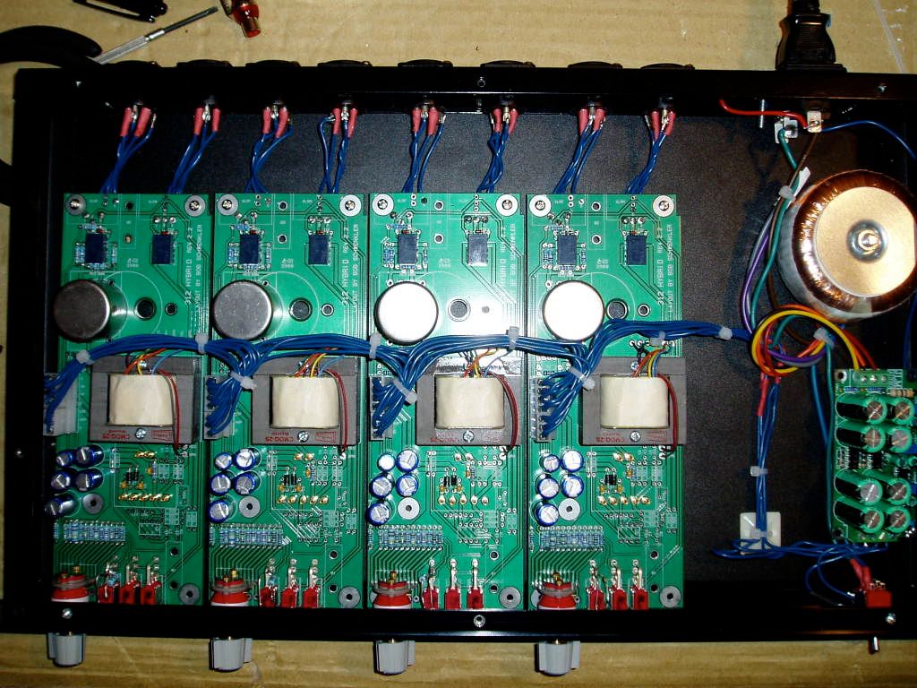
63.4 is actually the lowest value of a 12 step range from 63r4-20k. Depending on what orientation the board ends up being mounted in (generally either horizontally with components facing up or vertically with components facing right if you're looking at the PCB from the front) determines which spot on the PCB the range of resistors will begin. As an example, if I took the PCBs from the unit shown on my website and mounted them all flat I'd have to change the order of those resistors to get the volume knob to have low gain at the 6:30 position and high gain at the 5:30 position. This is what I'm referring to on the BOM when it says at the top that the gain resistors are ordered for vertical PCB mounting.

Did you stuff the resistors exactly as specified on my BOM and are you also mounting your boards horizontally? It sounds to me like this may be the case and if so, your lowest and highest gain settings would be at 3:30 and 2:30, respectively (I think, I'm trying to visualize it in my head...).

Also, the lowest value resistors are giving you the most gain as there is less signal being applied to the inverting input of the op amp (less negative feedback=more gain).

I'm using DIY 990s in my boards, the PTownkid kits. I haven't heard of the opamp you mention.

Did you space the output transformer off of the PCB? I sent out an email about this potential issue mid-February. Your sound sample sounds exactly like what I heard with my units here. It can be easily remedied by spacing the output transformer a few mm off the PCB. 2-4 normal sized washers should do the trick if this is the issue. To test it out just try unmounting the transformer and setting it next to the board, or at least not in the mounting slot. It looks by your photos that there's enough lead length to do that. Test them out and if it's solved just remount them with the transformers spaced and you'll be fine.

guitarguy12387 said:
Ok got a chance to do some more testing today. And... got MORE weird results.

After double checking all my component placement again and cleaning up some solder joints, i tried tying pins 6 and 7 of the input tranny together and taking them directly to star ground point. I decided to do this because i had noticed that touching the can of the tranny significantly reduced all the noise at high and low gain values.

Here's the results: I pretty much get great sound at all gain settings except for the third position from counter clockwise (lowest gain) which still has lots of clicking/humming (oscillation i assume). Another weird thing is that the gain settings below this one (settings one and two) both are very high gain... which seems weird to me.

I have double checked (with a multimeter) that there are no shorts on any of the gain resistors and grayhill switch. I have also checked my R values many times. I cannot figure it out!!!
 
AHAAAAAAA! Finally!

So i removed the output transformer (even though i had already tried spacing it from the PCB by as many as 2 nuts), like you suggested, and perfect sound!! At all gain stages.  ;D

So yeah... i stuffed the resistors as you mentioned (and i plan on mounting vertically), but i have been testing horizontally. I guess i just assumed fully CCW was lowest and fully CW was highest gain settings.

Ah... i'm so glad that... after a solid 6months of working on this thing... it finally works! Ha.

Thanks again to EVERYONE for all the help. Especially bob... thanks for your patience and help. I will be buying some more of your boards soon :)
 
Great! Sorry it took this long to figure it out.

Happy recording!

guitarguy12387 said:
AHAAAAAAA! Finally!

So i removed the output transformer (even though i had already tried spacing it from the PCB by as many as 2 nuts), like you suggested, and perfect sound!! At all gain stages.  ;D

So yeah... i stuffed the resistors as you mentioned (and i plan on mounting vertically), but i have been testing horizontally. I guess i just assumed fully CCW was lowest and fully CW was highest gain settings.

Ah... i'm so glad that... after a solid 6months of working on this thing... it finally works! Ha.

Thanks again to EVERYONE for all the help. Especially bob... thanks for your patience and help. I will be buying some more of your boards soon :)
 
mikefatom said:
could someone tell me what the purpose of CDI1 (18pF) is?
...
From what I understand, it is simply a tone shaping cap. i.e. reduces bass at the DI input. Am I right?
...
The -3dB point of that RC (RDI1 and CDI1) network seems to be around 4kHz.
...
Is there a reason for the 4kHz figure?

I'd still like to know the answer to the above. Fabio maybe?  :)

Thanks,

Mike
 
Speaking of Fabio's DI's, do people have theirs working? I have 4 wired up with DIs in my 8 channel box and all of them are really noisy. I haven't spent a single moment troubleshooting them yet... I wonder if other people have run into the same isue?
 
bobschwenkler said:
Speaking of Fabio's DI's, do people have theirs working? I have 4 wired up with DIs in my 8 channel box and all of them are really noisy. I haven't spent a single moment troubleshooting them yet... I wonder if other people have run into the same isue?

I will let you know when my boards arrive...
 
Right then, I've got my first PCB layout designed for my preamp and I would greatly appreciate it if anyone had any tips or hints regarding it. An image of the layout is attatched. Just some notes on it. I have included a footprint for a Lundahl LL1587 Input & a Lundahl LL1517 Output as well as connections in case I decide to use a different output traffo. There is an attenuation pad after the output. The traces are all 1mm.

I also attatched a screenprint of the schematic because I'm sure I've overlooked somthing. I'm pretty certain that my load resistor is the incorrect value. The reason for this is because I am not clear on what the primary/secondary impedances are of the LL1587 are; the datasheet does ont make it clear to a newbotard like me. Looking at the 1587 datasheet (http://www.lundahl.se/pdfs/datash/1587.pdf) I see that it lists the "static resistance of each primary" as being 56 ohm, and the "static resistance of each secondary" as 600 ohm. I want to use the traffo as a 1:2 and so am assuming that the primary is wired in series giving me 112/600?. Someone please tell me where I am getting confused. What does this static resistance refer to?
 

Attachments

  • 312 Type PCB.JPG
    312 Type PCB.JPG
    164.2 KB
I just looked briefly and didn't look at the x-fo, but shouldn't the 6K8 resistors should be parallel with the input Hi and Lo, not series?
Jeff
 
The input trafo looks to be wired correctly for 1:2, (the audio-in, middle is pin 2 and right is pin 3, right?). But r15 should be about 6K.  Also, I would try it without a zobel first, then use if needed.
 
brazilianwonderboy said:
Right then, I've got my first PCB layout designed for my preamp and I would greatly appreciate it if anyone had any tips or hints regarding it. An image of the layout is attatched. Just some notes on it. I have included a footprint for a Lundahl LL1587 Input & a Lundahl LL1517 Output as well as connections in case I decide to use a different output traffo. There is an attenuation pad after the output. The traces are all 1mm.

Hi, I'm planning to use Lundahl transformers too! however, I'm not familiar with building recording pre's but I've build a couple of high gain guitar amps and I think you run the output trace too close to the input trace. This would cause feedback in a high gain amp but I'm not sure if it matters in this kind of preamps...

Best regards

Thomas
 
Hi,

I am planning to build a API 312 preamp but I'm about to get crazy reading this thread over an over again ??? I want to use lundahl or OEP's transformers with API2520 opamp. Which transformers should I choose as input/output? I've read somewhere that for the API2520 the transformer should be between 1:5 - 1:10..but what about the ohms? ..please help me on this one..

Oh..btw.I'll primary use the preamp to record drums and guitars

Best regards

Thomas
 
If you want something that's similar to original API transformers go to Cinemag and the the 75101A(suffix PC for PC mount version), and the CMOQ2-L output transformer.

I don't know a whole lot about Lundahl's line, but the 1538 is a popular choice as a cleaner input transformer.

What do you mean what about the ohms?
 
rrs said:
Well almost finished my first API.

Just waiting on opamps from Fabio.  ;D
Wondering what the maximum voltage the OpAmps can take? I've heard of a few people blowing theres and wondering what are the main causes of this???
P1010086.jpg

P1010087.jpg

Well finally got my Op Amp boards and are built. Installed all 4 channels but unfortunately all 4 are not passing audio but emitting a very high pitched (around 10-15K) squeal which changes in volume as I adjust gain pot. First few gain positions emit nothing then after about position 5 or 6 I get the squeal sound.

All Voltages are correct and have doubble checked all components on main board and Op Amp boards.
 
bobschwenkler said:
If you want something that's similar to original API transformers go to Cinemag and the the 75101A(suffix PC for PC mount version), and the CMOQ2-L output transformer.

I don't know a whole lot about Lundahl's line, but the 1538 is a popular choice as a cleaner input transformer.

What do you mean what about the ohms?

Hi, thank you for your reply:)

Cinemag transformers are not available in europe (..don't know where I can get them). The LL1538 has 200ohm:5k and the original API2622 has 150ohm:10k and I'm not sure how to or what to change in the schematic. I've seen your hybrid 312's with LL1538 wired 1:2 as input and JE990 as op-amp...but I want to use the API2520 circuit as op-amp.

I know I won't get the exact API sound..but who knows - it might sound even better with lundahls:)

Best regards

Thomas
 
You may need a zobel network with the Lundahl, so you'll need to look into that. Otherwise, the question you're asking was actually addressed on the previous page. You'll just need to determine the value of the input load resistor.

Cinemags are available direct from Cinemag.

The LL1538s in my boards are actually wired 1:2.5 (it can also be wired 1:5).
 
Wow. Long thread! I'm thinking of using the 312 as my next pre project. It will be only my second one. The first wasn't that bad (it was a Neve). I had a little extra money so I ordered the original, old iron and I already had some BA283AV boards.

Now, this 312 is starting to confuse me! :) I was happy when I saw the layout for the original 2520 board on Fabio's site. Glad someone decoded it! I plan on etching my boards. Can I use all of the layouts on Fabio's site (312 board, 2520, and PSU)? Or has someone found mistakes in them?

My second problem is the transformer issue.... I like to keep things (especially iron) as original as possible in a circuit. What are the best repros of the API trannys? Also, how much would it cost to buy original API trannys? Could they be more than Neve? Seems like Neve is hyped much more thus possibly priced higher. I also found what looks like an original 312 PCB etch card but I suspect it's too small, but I'm not 100% sure. I'll post it and then maybe someone with more knowledge than I can say so......
API_PCB_Cards.jpg


Back
Top