You are using an out of date browser. It may not display this or other websites correctly.
You should upgrade or use an alternative browser.
You should upgrade or use an alternative browser.
API 512b Schematic
- Thread starter OneRoomStudio
- Start date


Help Support GroupDIY Audio Forum:
This site may earn a commission from merchant affiliate
links, including eBay, Amazon, and others.
+100 ;Dmitsos said:whip out that camera!
I think we may need a secret handshake or special knock to view this thread! 8)
kazper
Well-known member
Just don't offer up the Gerber's to the guy walking up selling stuff out of his coat.
mitsos
Well-known member
- Joined
- May 4, 2007
- Messages
- 2,886
yeah, secret handshakes are bad news. They'll eventually cause problems. Look what happened with the VK1...
Keep this **** in the open, no harm... API should be helping their customers. If the Chinese (or anyone else) want to make an exact clone of the 512, all they have to do is buy one, they're cheap. Investment-wise, it makes total sense. I understand if they don't want to sell opamps, but schemos? in the old days, you'd get a schemo with your equipment. Look at all the old Urei manuals.
Keep this **** in the open, no harm... API should be helping their customers. If the Chinese (or anyone else) want to make an exact clone of the 512, all they have to do is buy one, they're cheap. Investment-wise, it makes total sense. I understand if they don't want to sell opamps, but schemos? in the old days, you'd get a schemo with your equipment. Look at all the old Urei manuals.
Biasrocks
Well-known member
OneRoomStudios said:API got back to me - and just as I suspected:
"I am sorry but I can't e-mail you schematic for 512b because it is very similar as current pre-amps (factory policy)."
I might have a chance to take some photo's tonight. The problem is with R8, which is connected to the Trim pin on the 2520.
That just sucks out loud, too similar to current products so no schematic???
Pulled my 512c, circa 1997
Reichenbach RE-115K-EPC on the input, good ole AP2503 on the output
2 Opamps in there and a 12volt relay, which I'm guessing switches input polarities.
The opamps are an LM3915N (18-pin dip) and a LF421CN (8-pin dip), which are in the same general
vacinity of each other and I'm guessing are both for the front panel LED metering circuit.
R8 is near the input transformer/relay on the 512c and appears to be a
19R 1% metal film, code Blue,Brown,White,Black Brown
I don't think it's the same resistor you're after for your 512b.
On the 512c there is no connection to the trim pin of the opamp, in fact I'm fairly
certain that the API 2520 that was in there originally and for sure the Avedis 1122
don't have that pin included on the opamp.
Where's Paul Wolff when you need him.

Mark
Biasrocks
Well-known member


Biasrocks
Well-known member

Biasrocks
Well-known member

Biasrocks
Well-known member

Biasrocks
Well-known member

mitsos
Well-known member
- Joined
- May 4, 2007
- Messages
- 2,886
Bias, you ROCK! ;D
but I can't believe for $900 they can't clean the topside of the board. :")
can you tell the value of the feedback cap?
The LF412(?) is probably some kind of rectifier for the 3915 (although I think there should be another 4148 somewhere?) What's the other diode?
No help on the trim.. Hopefully if you post pics someone can help with it.
but I can't believe for $900 they can't clean the topside of the board. :
can you tell the value of the feedback cap?
The LF412(?) is probably some kind of rectifier for the 3915 (although I think there should be another 4148 somewhere?) What's the other diode?
No help on the trim.. Hopefully if you post pics someone can help with it.
Biasrocks
Well-known member
mitsos said:Bias, you ROCK! ;D
but I can't believe for $900 they can't clean the topside of the board. :
can you tell the value of the feedback cap?
Yes, I noticed the flux residue on there. These were manufactured before the ATI handover, so I'm sure they look a bit different these days. :
Feedback cap, are you talking about the electrolytic cap C20, 2u2/50volt?
Mark
Biasrocks
Well-known member
mitsos said:no, c14, under the opamp.
EDIT: look different these days? Yeah they use a brighter blue soldermask...
C14 is a silver mica 10pf, 300v
DZ1 is a 1N47?? with "8.2v" printed on the circuit board.
So I'm thinking it's a 1N4738A.
Mark
Biasrocks
Well-known member
mitsos said:10pf
The code on the capacitor was 100J, 10pf 5%.
Mark
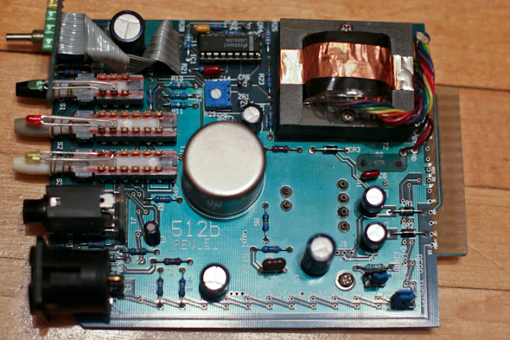
Sorry it took so long, here you go:
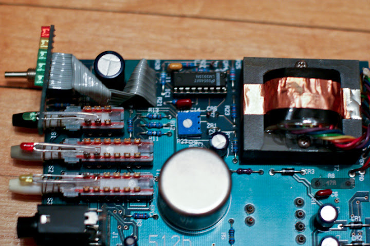
I darkened the area where the resistor burnt up. I thought it was connected to the trim pin because of this image I have:
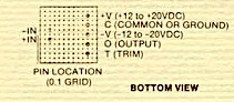
I think it may actually be the output pin. I'm guessing the 2520 is fried and I can probably just replace the resistor and pop a new one in, but I don't want to risk it until I know what else could be wrong....
I darkened the area where the resistor burnt up. I thought it was connected to the trim pin because of this image I have:
I think it may actually be the output pin. I'm guessing the 2520 is fried and I can probably just replace the resistor and pop a new one in, but I don't want to risk it until I know what else could be wrong....
Biasrocks
Well-known member
OneRoomStudios said:Sorry it took so long, here you go:
I darkened the area where the resistor burnt up. I thought it was connected to the trim pin because of this image I have
Oddly enough that data sheet appears to be reversed, the trim pin is actually on the left corner, not the right, it's the view if you look at the 2520 from the bottom instead of the top. If you look at the photo I posted (which I suspect you already did) which includes the Avedis 1122; that's the correct pin-out.
It looks like the value is printed on the circuit board, 47R.
That would be a 47 ohm 1% metal film resistor. I'd put a 1/2 watt-er in there to be safe.
Why not replace that resistor, power it up and take some voltage readings without the 2520 inserted to be sure you're in a safe range before you pop in the 2520.
Mark
Greg
Well-known member
What's the deal with the extra DIP-8 on the 512C by the meter driver circuit... I don't see it on the 512B.
Perhaps a servo?
Perhaps a servo?